Steam rotating heat conduction sludge drying device

A technology of sludge drying and steaming, which is applied in water/sludge/sewage treatment, dehydration/drying/concentrated sludge treatment, special treatment targets, etc. Affect the drying rate and other issues, to achieve the effect of increasing the amount of dried mud, simple structure, and prolonging the reversal time

Active Publication Date: 2015-07-29
WUXI GUOLIAN ENVIRONMENTAL SCI & TECH
View PDF4 Cites 3 Cited by
  • Summary
  • Abstract
  • Description
  • Claims
  • Application Information

AI Technical Summary

Problems solved by technology

[0004] In summary, the steam indirect heating sludge drying device has the following technical problems: 1. The condensed water in the hollow shaft will flow back into the blades, which will affect the drying rate; In order to solve this problem, the dry sludge is usually back-mixed to the sludge inlet, so that the moisture content of the sludge entering the dryer is lower than the moisture content in the viscous zone. Because the moisture content of the wet sludge is relatively high, the amount of back-mixing is extremely high. Large, affecting thermal efficiency; 3. The amount of returned material is not easy to control, affecting operation

Method used


Image

  • Steam rotating heat conduction sludge drying device
  • Steam rotating heat conduction sludge drying device
  • Steam rotating heat conduction sludge drying device

Examples


Embodiment 1

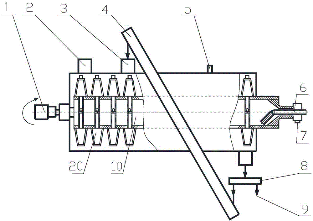
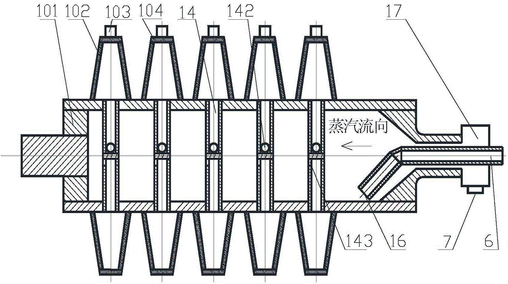
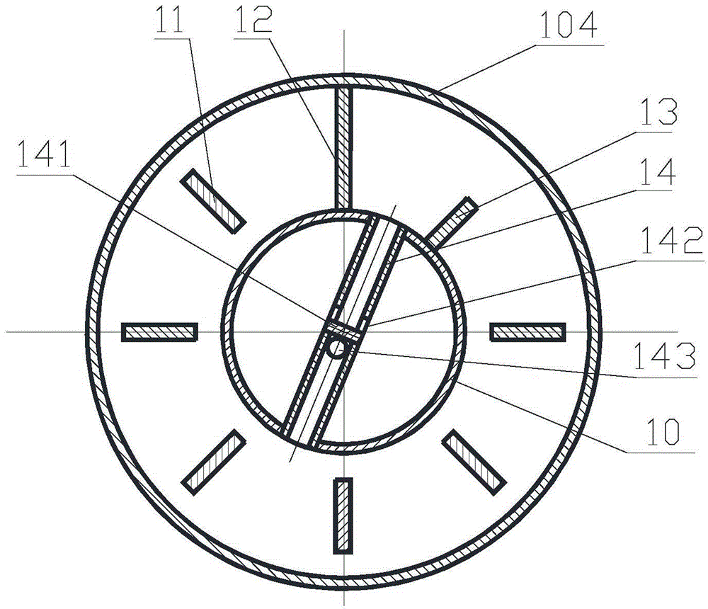
[0021] A steam-type sludge drying device is composed of a rotary heat conduction dryer, a dry sludge distributor 8, a dry sludge lifter 4, etc. The sludge inlet 2 is located above one end of the dryer, and the dry sludge distributor 8 is located at the other end of the dryer. On the side or bottom of one end, the upper outlet of the dry sludge lifter 4 is connected to the sludge return port 3. There are multiple inlets on the upper part of the dryer to adjust the position of the sludge return port. The sludge return port 3 is located on the sludge above the dryer. Viscous zone paddle. One end of the dry mud distributor 8 is provided with a dry mud outlet 9, and the other end is connected to the inlet of the dry mud lifter 4, and the amount of returned material is quantitatively adjusted by the time when the dry mud distributor 8 reverses. A plurality of blades 20 are arranged on the hollow shaft 10, and the blades are composed of two side plates 102 and a top plate 104. Each b...

Embodiment 2

[0024] A hollow shaft 10 for implementing the above-mentioned sludge drying device. The difference from Embodiment 1 is that each paddle 20 is provided with a steam inlet and drain pipe 14 and a paddle steam inlet pipe 15, and there is a certain distance between them. The angle is generally 90°, and they are arranged in front and back in the axial direction, and they are close to each other. The air inlet 143 of the paddle is parallel to the hollow shaft 10 and is set against the steam inlet direction. The outlet 142 of the blade is a total of 2 through holes Perpendicular to the hollow shaft 10, this structure is suitable for extra large paddles.

[0025] The working process of the device of the present invention is as follows:

[0026] The hollow shaft 10 of the dryer is driven by the motor reducer 1, and the wet sludge is sent into the dryer from the wet sludge inlet 2. The steam is sent into the hollow shaft through the steam inlet 7 of the rotary joint 17, and enters eac...


PUM


Abstract

A steam heating type sludge drying device comprises a rotating heat conduction drier, a dried sludge distributor, a dried sludge lifter and the like, wherein dried sludge returns to a variable sludge return opening; the dried sludge distributor is utilized for precisely controlling the sludge moisture at the back of the sludge return opening to be lower than the moisture in a viscous area; a plurality of blades are connected onto a hollow shaft; a blade closure plate, a blade water collecting plate and blade reinforcing ribs are arranged in each blade; specially designed blade steam inlet water discharge pipes penetrate through the hollow shaft between the blade closure plates and the blade water collecting plates, so that blade steam inlet pipes and water discharge openings are all close to the center of the hollow shaft, condensate water in the hollow shaft is prevented from backwards flowing into the blades, and water flowing from the blades is prevented from directly entering blade steam inlets. In the frame structure of the steam heating type sludge drying device, the hollow shaft is high in rigidity and strength; the backward flowing of the condensate water is avoided; the dried sludge return amount is small; the unit area dry sludge amount is large.

Description

technical field [0001] The invention belongs to the field of sludge drying treatment, and relates to a steam indirect heating type drying device, in particular to a steam type rotary heat conduction drying device for treating sludge. Background technique [0002] During the drying process of the sludge, when the moisture content is lower than a certain value (the upper limit of the viscous zone), the viscous phenomenon begins to appear, which is manifested by the increase of the shaft torque, the drying rate is low, and it is not easy to dry, and then drops to another value ( After the lower limit of the viscous zone), the sludge stickiness disappears. In order to avoid the sticky phenomenon, the following two methods are usually used to solve it: (1) Control the moisture content of the dry sludge to be higher than the upper limit of the viscous zone, which is called semi-dry (2) Return the dry sludge to the wet sludge inlet and mix it with the wet sludge so that the moistur...

Claims


Application Information

Patent Timeline
Patent Type & Authority Applications(China)
IPC IPC(8): C02F11/12
CPCC02F11/12C02F2303/06
Inventor 葛仕福杨叙军宋联朱葛
Owner WUXI GUOLIAN ENVIRONMENTAL SCI & TECH
Why Eureka
Try Eureka