Canister

A carbon canister and canister technology, which is applied in the field of engine fuel evaporation control accessories, can solve the problems of difficult emission standards, poor adsorption and desorption effects, and inability to fully and effectively utilize carbon powder adsorption and desorption performance.

Active Publication Date: 2017-08-08
金华市合发科技有限公司
View PDF12 Cites 3 Cited by
  • Summary
  • Abstract
  • Description
  • Claims
  • Application Information

AI Technical Summary

Problems solved by technology

[0003] However, the existing carbon canisters have the following deficiencies during use: the carbon canister cannot fully and effectively utilize the carbon powder adsorption and desorption performance during adsorption and desorption, the adsorption and desorption effects are poor, and the emission is difficult to meet the standards

Method used


Image

  • Canister
  • Canister
  • Canister

Examples


Embodiment 1

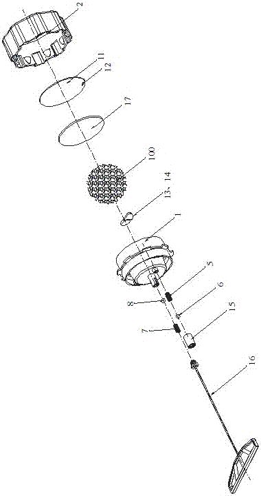
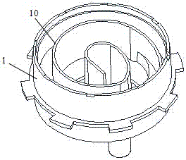
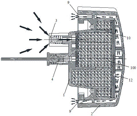
[0027] This embodiment provides a carbon tank, such as Figure 1-6 As shown, the tank body is composed of a body 1 and an upper cover 2 that are interlocked with each other. The adsorption port 3 and the desorption port 4 are located on the body 1 .

[0028] The adsorption port 3 is provided with a one-way valve for oil and gas to enter the tank, and the one-way valve includes a first spring 5 , a first steel ball 6 and a small cap 15 .

[0029] The desorption port 4 is provided with a one-way valve for discharging oil and gas in the tank, and the one-way valve includes a second spring 7 , a second steel ball 8 and a pull wire 16 .

[0030] The air opening 9 is a gap between the body 1 and the upper cover 2 .

[0031] A bent plate 10 is arranged in the body 1, and the bent plate 10 is arranged in a spiral shape with a gradually increasing bending radius. Carbon powder 100 is filled in the body 1 and distributed along the channel formed by the bent plate 10. . A partition 11...

Embodiment 2

[0038] Such as Figure 7 As shown, the spacer assembly includes a folded plate 800, and the folded plate is arranged in a spiral shape with a gradually increasing bending radius. The plate unit 800a is bent in the same direction, and the entire folded plate 800 is arranged in a spirally outwardly expanded form.

Embodiment 3

[0040] The spacer assembly includes at least two staggered spacer plates, such as Figure 8 As shown, there are four partitions in this embodiment, and the staggered arrangement means: the first partition 701 starts from the first side 790a of the inner wall of the tank body 790 and faces in the direction opposite to the first side 790a The second side 790b of the inner wall of the tank body 790 extends until close to the second side 790b, the second partition plate 702 is spaced apart from the first partition plate 701, and the second partition plate 702 starts from the first The two sides 790b extend toward the first side 790a until close to the first side 790a.


PUM


Abstract

The invention discloses a carbon tank, which comprises a tank body, an adsorption port, a desorption port and an air port located on the tank body. The tank body is provided with an accommodating cavity, and the accommodating cavity is separated into a continuous channel by a spacer assembly. Carbon powder is arranged in the channel, the adsorption port and the desorption port are located at one end of the channel, and the atmospheric port is located at the other end of the channel. With the above technical solution, oil and gas will gradually spread along the channel after entering the accommodation cavity, and dividing the accommodation cavity into channels can increase the path of oil and gas spreading as much as possible under the condition of constant volume, so that it can be absorbed by the channels in the channel. The carbon powder is fully adsorbed to achieve good adsorption and desorption effects.

Description

technical field [0001] The invention relates to an engine fuel evaporation control accessory, in particular to a carbon canister for fuel evaporation adsorption and desorption. Background technique [0002] The carbon canister is generally installed between the fuel tank and the engine. Since fuel is a volatile liquid, the fuel tank is often full of vapor at normal temperature, and the role of the fuel evaporative emission control system is to introduce the vapor into combustion and prevent it from volatilizing into the atmosphere. An important part of this process is the activated carbon canister storage device. Because activated carbon has an adsorption function, for example: when the car is running or turned off, the gasoline vapor in the fuel tank enters the upper part of the activated carbon tank through the pipeline, and the fresh air enters the activated carbon tank from the lower part of the activated carbon tank. After the engine is turned off, gasoline vapor and ...

Claims


Application Information

Patent Timeline
Patent Type & Authority Patents(China)
IPC IPC(8): F02M25/08
Inventor 邵志强肖相德
Owner 金华市合发科技有限公司
Why Eureka
Try Eureka