Double-pendulum head structure driven by differential double motors

A differential drive and double swing head technology, applied in the direction of differential transmission, mechanical equipment, transmission devices, etc., can solve the problems of reduced reliability of backlash elimination, unsuitable large-angle swing, and limited swing head swing range, etc. Quality, the effect of ensuring motion accuracy

Inactive Publication Date: 2015-07-29
NORTHEASTERN UNIV
View PDF7 Cites 9 Cited by
  • Summary
  • Abstract
  • Description
  • Claims
  • Application Information

AI Technical Summary

Problems solved by technology

[0003] At present, the existing A / B-axis double swing heads are mostly driven by worm gears, and the two sets of worm gears are coaxially arranged, and a certain preload is applied by loading a butterfly spring or an adjustment sleeve on one end of the worm, so that the transmission gear It forms a reverse mesh with the fan-shaped rack at the output end, thereby eliminating the transmission gap and improving the transmission accuracy, but this mechanical anti-backlash method will gradually reduce the reliability of the anti-backlash with the increase of time
[0004] In addition, the drive mode of the rotary servo motor accelerator and decelerator adopted by the existing A / B-axis double-swing head leads to a complex and bulky mechanical structure of the A / B-axis double-swing head, and the movement of the center of the swing head during the swing process will cause Additional torque, which often needs to be balanced by a hydraulic cylinder, therefore, the existing A / B-axis double swing head should not swing at a large angle, thus limiting the swing range of the swing head

Method used


Image

  • Double-pendulum head structure driven by differential double motors
  • Double-pendulum head structure driven by differential double motors

Examples


Embodiment Construction

[0022] The present invention will be further described in detail below in conjunction with the accompanying drawings and specific embodiments.

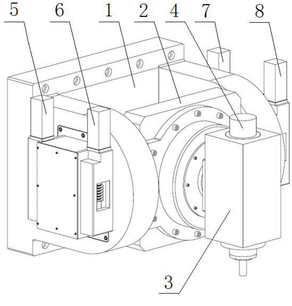
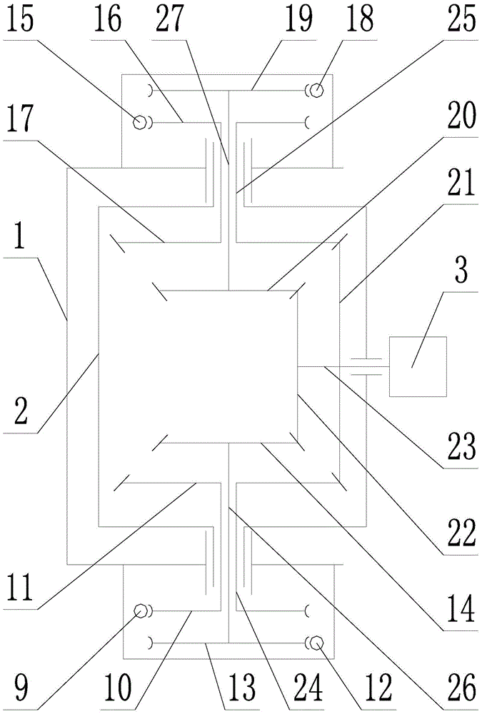
[0023] Such as figure 1 , 2 As shown, a double swing head structure with dual motor differential drive, including U-shaped support 1, pitch swing shaft 2, first differential input unit, second differential input unit, differential output unit, headstock 3, Main shaft motor 4 and rotary pendulum shaft 23; the first differential input unit includes a first active servo motor and a reducer 5, a first driven servo motor and a reducer 6, a first driving worm 9, and a first driving worm 10 , the first driving bevel gear 11, the first driven worm 12, the first driven worm gear 13, the first driven bevel gear 14, the first hollow shaft 24 and the first driven shaft 26; the second differential input The unit includes the second active servo motor and speed reducer 7, the second driven servo motor and speed reducer 8, the second driving worm ...


PUM


Abstract

The invention relates to a double-pendulum head structure driven by differential double motors. Both a first differential input unit and a second differential input unit are driven by double motors, so that pendulum heads have large tilt angles and torques, the driving motors and speed reducers of the two differential input units are arranged on the outer side of a U-shaped support, and moving members of the pendulum heads only include pitching pendulum shafts, rotary pendulum shafts on the pitching pendulum shafts, main shaft boxes and main shaft motors, so that the mass of the moving members of the pendulum heads is integrally reduced. The equal torques in opposite directions are loaded between a driving servo motor and a driven servo motor, so as to form certain torque difference; due to the existence of the torque difference, driving bevel gears of the differential input units are reversely engaged to a driving bevel gear of a differential output unit; under the action of reverse engagement, the transmission clearance of the differential input units is smoothly eliminated, so that non-clearance transmission of the differential input units is realized. Through the non-clearance transmission of the first differential input unit and the second differential input unit, the kinematic accuracy of the pendulum heads is guaranteed ultimately.

Description

technical field [0001] The invention relates to an A / B-axis double swing head structure in a numerical control machine tool, in particular to a double swing head structure driven by a double motor differential drive. Background technique [0002] CNC machine tools with A / B-axis double pendulum heads can meet the cutting requirements of special curved surfaces, especially five-axis linkage CNC milling machines with A / B-axis double pendulum milling heads, which have been widely used in aircraft manufacturing and other fields. [0003] At present, the existing A / B-axis double swing heads are mostly driven by worm gears, and the two sets of worm gears are coaxially arranged, and a certain preload is applied by loading a butterfly spring or an adjustment sleeve on one end of the worm, so that the transmission gear It forms a reverse mesh with the fan-shaped rack at the output end, thereby eliminating the transmission backlash and improving the transmission accuracy, but this mech...

Claims


Application Information

Patent Timeline
Patent Type & Authority Applications(China)
IPC IPC(8): F16H37/04F16H48/12F16H57/023
CPCF16H37/04F16H48/12F16H57/023F16H2057/126
Inventor 房立金孙龙飞
Owner NORTHEASTERN UNIV
Why Eureka
Try Eureka