Non-Destructive Evaluation of Structures Using Motion Magnification Technology

A non-destructive, motion-amplifying technology that can be used in machine/structural component testing, material analysis using sonic/ultrasonic/infrasonic waves, strength properties, etc., and can solve problems such as expensive

Inactive Publication Date: 2015-07-29
THE BOEING CO
View PDF8 Cites 5 Cited by
  • Summary
  • Abstract
  • Description
  • Claims
  • Application Information

AI Technical Summary

Problems solved by technology

[0005] For strain measurement applications such as structural testing, strain gages require

Method used


Image

  • Non-Destructive Evaluation of Structures Using Motion Magnification Technology
  • Non-Destructive Evaluation of Structures Using Motion Magnification Technology
  • Non-Destructive Evaluation of Structures Using Motion Magnification Technology

Examples


Embodiment Construction

[0025] Embodiments of systems and methods for performing non-destructive assessment of structures using motion magnification techniques will now be described. The following systems and methods for monitoring structural testing using motion magnification techniques will be described.

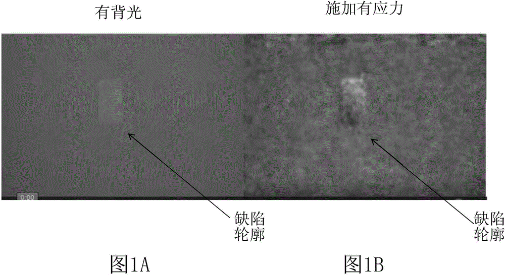
[0026] To prove the concept of using motion magnification techniques to perform non-destructive evaluation of structures, tests were performed in which a 3 / 4 inch by 1 inch defect was machined into the backside of a 1 / 8 inch thick composite layup. In the first part of the test, light was applied to the back of the stack and a video was recorded of the area on the anterior skin overlapping the machined defect. Figure 1A is a screencast video image of a backside lit stackup showing the outline of a machined defect, which would normally not be visible from the front. In the second part of the test, strain was created (ie, stress was applied) using a partial vacuum source attached to the backside of...


PUM


Abstract

In one process, a mechanical stress (quasi-static or dynamic) or thermal stress is introduced into a local area of a structure where damage is suspected. A standard (or high speed for some dynamic stress approaches) video recording is made of the area under test. The video is processed using a motion amplification algorithm which magnifies extremely small motions. The motion amplification can reveal strains (for static or thermal loading) or wave patterns (for dynamic loading) generated on the surface of the part. If there is damage or structural change, the resulting surface strains will indicate it, or the surface waves in that area will change in phase, amplitude, or both, and will be indicated in the video images. In another process, motion magnification is used to highlight local failure events during structural testing.

Description

technical field [0001] The present disclosure generally relates to apparatus and methods for non-destructive evaluation and testing of structures. Background technique [0002] Non-destructive evaluation of a structure involves examining the structure in its entirety without damaging the structure or requiring major dismantling of the structure. Non-destructive assessments are commonly used in the aircraft industry to inspect aircraft structures for defects in the structure or any type of internal or external damage. Non-destructive evaluation is also used in the initial fabrication of aircraft structural components. This ensures that the part is manufactured correctly and that no foreign objects are embedded in the part. Inspections may be performed during manufacture of the structure and / or after the structure has been put into service. [0003] Known NDE techniques include laser offset speckle technique and electron speckle interferometry (ESPI). Laser offset speckle ...

Claims


Application Information

Patent Timeline
IPC IPC(8): G01N3/00G01N3/06
CPCG01N3/068H04N7/183G01N21/8803G01N21/8851G01N29/045G01N2291/2694G01M5/0033G01M5/0066G01M5/0075G01M5/0091
Inventor W·J·塔皮亚G·E·乔治森
Owner THE BOEING CO
Why Eureka
Try Eureka