Measuring system and method for refractive index of optical material

An optical material and measurement system technology, applied in the measurement of phase influence characteristics, etc., can solve the measurement system measurement accuracy laser power fluctuation, air disturbance and vibration influence, can not meet the development needs of high refractive index materials and new materials, limit samples Refractive index range and measurement accuracy, etc., to achieve the effect of strong environmental anti-interference, low cost and simple operation

Inactive Publication Date: 2017-07-18
TSINGHUA UNIV
View PDF3 Cites 0 Cited by
  • Summary
  • Abstract
  • Description
  • Claims
  • Application Information

AI Technical Summary

Problems solved by technology

However, these two methods have a limited measurement range (1.3-1.7), and require matching liquids or matching prisms, etc., which limit the refractive index range and measurement accuracy of the sample, and cannot meet the development needs of large refractive index materials and new materials.
[0004] In addition, the measurement accuracy of the measurement system in the prior art is also easily affected by laser power fluctuations, air turbulence and vibration, and has strict requirements on the environment

Method used


Image

  • Measuring system and method for refractive index of optical material
  • Measuring system and method for refractive index of optical material
  • Measuring system and method for refractive index of optical material

Examples


Embodiment Construction

[0030] The measurement system and method for measuring the refractive index of optical materials provided by the present invention will be described in detail below in conjunction with the accompanying drawings.

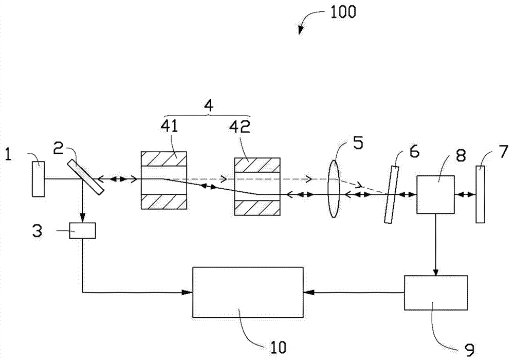
[0031] see figure 1 The optical material refractive index measurement system 100 provided by the embodiment of the present invention includes a laser module 1, a beam splitter 2, a photoelectric detection module 3, an acoustic optical frequency shift module 4, a reference feedback mirror 6, and a measurement Feedback mirror 7 , a displacement device 8 , a displacement detection device 9 and a signal processing system 10 .

[0032] The laser module 1 is used to output laser light. The laser module 1 can be a full inner cavity, a half outer cavity or a full outer cavity, can use a solid-state laser or a semiconductor laser, and can output laser light continuously. Preferably, the working mode of the laser module 1 is a single longitudinal mode and a fundamental trans...


PUM

PropertyMeasurementUnit
transmittivityaaaaaaaaaa
reflectanceaaaaaaaaaa

Abstract

The invention provides a measuring system of a refractive index of an optical material. The measuring system comprises a laser module, a light splitter, a photoelectric detection module, a signal processing system, an acousto-optic frequency shift module, a reference feedback mirror, a measuring feedback mirror, a displacement device and a displacement measuring system, wherein the light splitter splits laser light output by a laser into reflected light and transmission light; the photoelectric detection module converts the reflected light into an electrical signal; the signal processing system processes the electrical signal input by the photoelectric detection module; the acousto-optic frequency shift module carries out frequency shift on the transmission light to form reference light and measuring light; the reference feedback mirror reflects the reference light to allow the reference light to return along a light path of the measuring light outgoing from the acousto-optic frequency shift module; the measuring feedback mirror and the reference feedback mirror are arranged at an interval; the measuring light outgoing from the reference feedback mirror is reflected by the measuring feedback mirror and then returns along the original light path; the displacement device is used for bearing a sample to be measured and driving the sample to be measured to displace; and the displacement measuring system is used for detecting the displacement delta 1 of the sample to be measured and imports a measuring result into the signal processing system. The invention more provides a measuring method of the refractive index of the optical material.

Description

technical field [0001] The invention relates to the technical field of laser measurement, in particular to a measurement system and a measurement method for the refractive index of optical materials. Background technique [0002] Refractive index is one of the most important optical parameters of materials, and its accuracy is the basis of optical system design and manufacture. The precise measurement of the refractive index is of great significance in optical design, gem identification, liquid concentration, purity identification, food, medicine, chemical industry and other fields. [0003] At present, the existing refractive index measurement methods are mainly divided into two categories: goniometric method and interferometric method. Among them, the minimum deflection angle method has the highest measurement accuracy and is used as a national standard in the Metrology Institute. However, this method has extremely high requirements on the processing accuracy of the samp...

Claims


Application Information

Patent Timeline
Patent Type & Authority Patents(China)
IPC IPC(8): G01N21/41
Inventor 张书练徐玲谈宜东
Owner TSINGHUA UNIV
Why Eureka
Try Eureka