Refrigerant circuit for a vehicle air-conditioning system and method of air-conditioning a vehicle interior

A refrigerant circuit and vehicle air-conditioning technology, which is applied to vehicle components, refrigeration and liquefaction, refrigerators, etc., can solve the problems of small waste heat of vehicle engines, high energy consumption, and the impossibility of meeting vehicle heating, so as to reduce expenditure and cost Effect

Inactive Publication Date: 2015-07-29
VALEO KLIMASYST
View PDF6 Cites 5 Cited by
  • Summary
  • Abstract
  • Description
  • Claims
  • Application Information

AI Technical Summary

Problems solved by technology

[0003] However, during the warm-up phase in the case of electric vehicles as a whole, and in the case of motor vehicles with internal combustion engines, the waste heat from the vehicle's engine is so small that it is impossible to satisfy the heating of the vehicle interior
For this, an additional electric heating device is often used, but this is associated with a very high energy consumption and also with an additional requirement for installation space and with additional equipment costs

Method used


Image

  • Refrigerant circuit for a vehicle air-conditioning system and method of air-conditioning a vehicle interior
  • Refrigerant circuit for a vehicle air-conditioning system and method of air-conditioning a vehicle interior
  • Refrigerant circuit for a vehicle air-conditioning system and method of air-conditioning a vehicle interior

Examples


Embodiment Construction

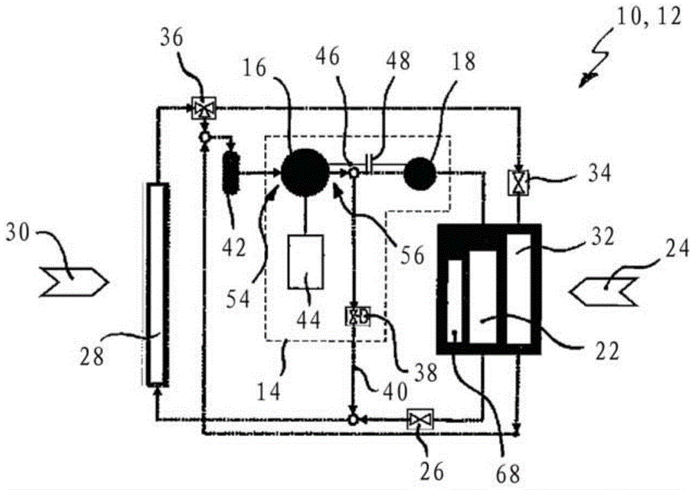
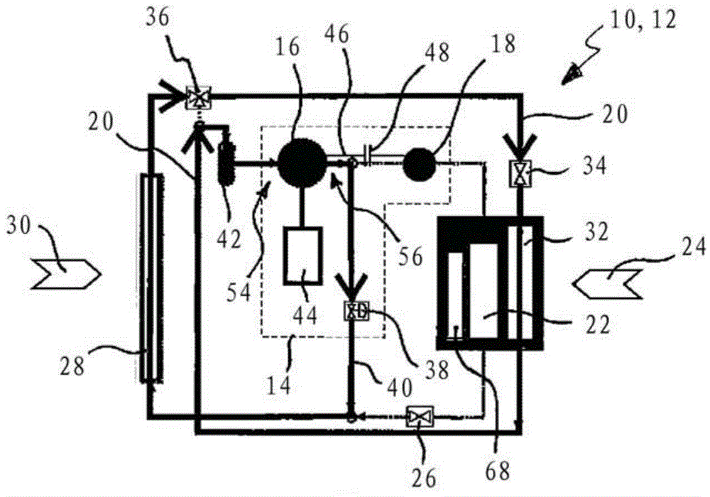
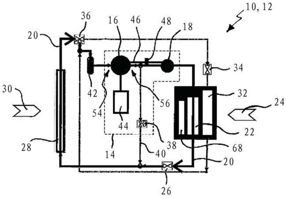
[0032] figure 1 A refrigerant circuit 10 of a vehicle air conditioning system 12 is shown, in particular for an electric vehicle, comprising a compressor unit 14 comprising a first compressor 16 and a second compressor 18 arranged downstream for compressing refrigerant 20; condenser 22 for cooling and condensing refrigerant from compressor unit 14, and for heating air 24 which can be supplied to the interior of the vehicle; first pressure reducing unit 26 arranged at the side of condenser 22 Downstream, for depressurizing the refrigerant 20 from the condenser 22; a heat exchanger 28 through which the refrigerant flows for heat exchange with vehicle ambient air 30, and optionally for cooling and condensation or heat and evaporate the refrigerant 20; the evaporator 32 for heating and evaporating the refrigerant 20 and for cooling the air 24 that can be supplied to the interior of the vehicle; and the second pressure reducing unit 34 arranged upstream of the evaporator 32 , for ...


PUM


Abstract

The invention relates to a refrigerant circuit (10) of a vehicle air-conditioning system (12), in particular for electric vehicles, comprising a compressor unit (14) which includes a first compressor (16) and a second compressor (18) arranged downstream for compressing a refrigerant (20), a condenser (22) for heating air (24) which can be supplied to a vehicle interior, a first pressure reducing unit (26) arranged downstream of the condenser (22) for decompressing the refrigerant (20) from the condenser (22), a heat exchanger (28) through which refrigerant flows for heat exchange with vehicle ambient air (30), an evaporator (32) for cooling air (24) which can be supplied to a vehicle interior, and a second pressure reducing unit (34) arranged upstream of the evaporator (32) for decompressing the refrigerant (20) from the heat exchanger (28), the second compressor (18), the condenser (22) and the first pressure reducing unit (26) being bypassed in a cooling mode of the vehicle air-conditioning system (12), and the evaporator (32) and the second pressure reducing unit (34) being bypassed in a heating mode of the vehicle air- conditioning system (12).The invention furthermore relates to a method of air-conditioning a vehicle interior, in particular by means of the refrigerant circuit (10) described above.

Description

technical field [0001] The invention relates to a refrigerant circuit of a vehicle air-conditioning system, in particular for an electric vehicle, and to a method for air-conditioning a vehicle interior, in particular by means of such a refrigerant circuit. Background technique [0002] Modern motor vehicles are nowadays often equipped with an air conditioning system for air conditioning the vehicle interior. These vehicle air-conditioning systems are mainly based on the Carnot principle and operate through a refrigerant circuit to achieve cooling of the vehicle interior when there is a high external temperature. To heat the vehicle interior when the outside temperature is low, waste heat from the internal combustion engine of the motor vehicle is usually used. [0003] However, during the warm-up phase in the case of electric vehicles as a whole, and in the case of motor vehicles with internal combustion engines, the waste heat from the vehicle's engine is so small that su...

Claims


Application Information

Patent Timeline
Patent Type & Authority Applications(China)
IPC IPC(8): B60H1/00F25B1/10B60H1/32
CPCB60H1/00392F25B2500/01B60H1/00914F25B1/10B60H1/323F25B2341/0662B60H1/3223B60H1/00921F25B41/39
Inventor M.桑德曼R.豪斯曼
Owner VALEO KLIMASYST
Why Eureka
Try Eureka