Heat radiation assembly and electric device

A technology for heat dissipation components and electronic equipment, which is applied in circuits, electrical components, electric solid devices, etc., and can solve problems such as poor heat dissipation performance

Active Publication Date: 2015-07-29
HUAWEI DEVICE CO LTD
View PDF17 Cites 66 Cited by
  • Summary
  • Abstract
  • Description
  • Claims
  • Application Information

AI Technical Summary

Problems solved by technology

[0005] Embodiments of the present invention provide a heat dissipation component and electronic equipment to solve the technical problem of relatively poor h

Method used


Image

  • Heat radiation assembly and electric device
  • Heat radiation assembly and electric device
  • Heat radiation assembly and electric device

Examples


Embodiment 1

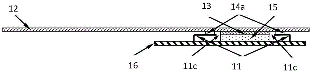
[0083] Please refer to figure 1 , the embodiment of the present application provides a heat dissipation assembly, the heat dissipation assembly includes:

[0084] A shielding element 11, the shielding element 11 is provided with a through hole 11c, the shielding element 11 is electrically connected to the ground copper of the PCB board 16, and the PCB board 16 is provided with a heating electronic element 15;

[0085] The heat pipe 12 is located on the through hole 11c, the heat pipe 12 is electrically connected to the shielding element 11, wherein the heat pipe 12, the PCB board 16 and the shielding element 11 form a heat pipe for accommodating the heat Electromagnetic shielding cover of electronic component 15;

[0086] The first elastic thermal interface material 13 is located between the heat pipe 12 and the heat-generating electronic component 15 , and adheres to the heat pipe 12 and the heat-generating electronic component 15 .

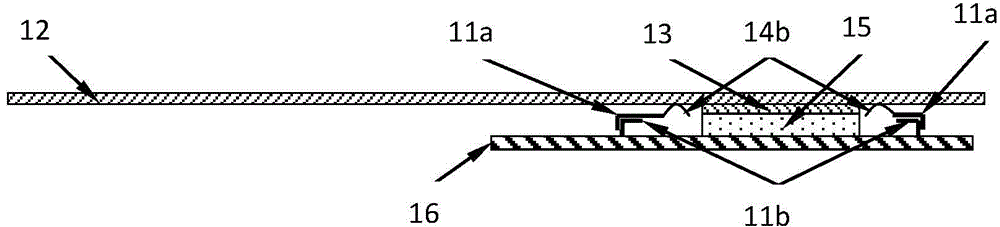
[0087] Please refer to figure 2 The s...

Embodiment 2

[0101] Please refer to Image 6 , the embodiment of the present application provides a heat dissipation assembly, the heat dissipation assembly includes:

[0102] A shielding element 11, the shielding element 11 is provided with a through hole 11c, the shielding element 11 is electrically connected to the ground copper of the PCB board 16, and the PCB board 16 is provided with a heating electronic element 15;

[0103] The elastic conductive thermal interface material 19 is located on the through hole 11c and is attached to the shielding element 11, wherein the elastic conductive thermal interface material 19, the PCB board 16 and the shielding element 11 form a An electromagnetic shielding cover for accommodating the heating electronic components 15;

[0104] The heat pipe 12 is located on the elastic conductive thermal interface material 19 and attached to the elastic conductive thermal interface material 19 .

[0105] like Image 6 As shown, the elastic conductive thermal...

Embodiment 3

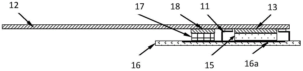
[0112] Please refer to Figure 8 , the embodiment of the present application provides a heat dissipation assembly, the heat dissipation assembly includes:

[0113] The heat-conducting metal block 17 is arranged on the PCB board 16, and is connected to the heating electronic component 15 provided on the PCB board 16 through the heat-conducting layer 16a on the PCB;

[0114] An elastic thermal interface material 18 is pasted on the heat-conducting metal block 17;

[0115] The heat pipe 12 is pasted on the elastic thermal interface material 13 .

[0116] During practical application, since the PCB board 16 is provided with many copper layers and thermal holes, most of the heat of many heat-generating electronic components 15 is transferred to the PCB board 16 . Therefore, in the embodiment of the present application, for the case where the main heat is transferred to the PCB board 16, a heat-conducting metal block 17 is arranged on the PCB board 16 adjacent to the heating elect...


PUM


Abstract

The invention provides a heat radiation assembly and an electric device, wherein the heat radiation assembly comprises: a screening element which is arranged with a through hole thereupon and is in electrical connection with ground copper of PCT board, the PCT board being equipped with heat radiation electrical elements; a heat tube which is positioned on the through hole, the heat tube being in electrical connection with the screening element, together, the heat tube, the PCT board and the screening element constituting an electromagnetic screen cover which can hold a heat radiation electrical element; an elastic thermal interface material which is arranged between the heat tube and the heat radiation electrical element and is cemented to the heat tube and the heat radiation electrical element. In the technical solution herein, the through hole on the screen element cements the thermal interface material on the heat radiation electrical element and the heat tube, which enables heat of the heat radiation electrical element to be transmitted to the heat tube via thermal interface material, thus reducing heat resistance of the heat radiation assembly and shortening heat transmission path between the heat radiation electrical element and the heat tube.

Description

technical field [0001] The invention relates to the technical field of heat dissipation, in particular to a heat dissipation component and electronic equipment. Background technique [0002] With the rapid popularization of LTE (Long Term Evolution) technology, the mobile Internet will provide high-definition, high-performance multimedia applications, which will lead to rapid growth of mobile data services, and the power consumption of mobile terminal equipment will also increase significantly. Thermal design within the space presents unprecedented challenges. [0003] In the prior art, the heat dissipation components used for the heating chip in the mobile terminal mainly include: the first thermal interface material, the shielding case / shielding box, the second thermal interface material and the heat pipe, the first thermal interface material, the shielding case / shielding box , the second thermal interface material and the heat pipe are sequentially stacked on the heating...

Claims


Application Information

Patent Timeline
IPC IPC(8): H05K7/20
CPCH01L23/427H01L23/552H01L2924/0002H01L2924/00H01L23/3675H01L23/3736H01L23/3737
Inventor 靳林芳肖永旺王国平邹杰李华林
Owner HUAWEI DEVICE CO LTD
Why Eureka
Try Eureka