Method for processing V-shaped groove of stainless steel composite plate

A processing method, stainless steel technology, applied in the field of metal cutting, can solve problems such as tool damage, poor austenite stability, and low work efficiency, and achieve the effects of high milling precision, low planing resistance, and high work efficiency

Inactive Publication Date: 2015-08-05
上海斯诺博建筑科技有限公司
View PDF3 Cites 4 Cited by
  • Summary
  • Abstract
  • Description
  • Claims
  • Application Information

AI Technical Summary

Problems solved by technology

[0002] With the rapid development of decorative materials, various composite decorative panels abound, and stainless steel composite panels are one of them. Ordinary stainless steel composite panels are composed of PVC panels or stainless steel honeycomb panels sandwiched between two layers of stainless steel panels. Stainless steel composite panels are used in At the same time, it is necessary to process a V-shaped groove on a layer of stainless steel panels and interlayer plates. In order to ensure the accuracy of the geometric shape of the V-shaped groove, forming end mills or horizontal milling cutters are often used for cutting. During the cutting process, cutting is difficult and The work efficiency is low, especially because of the relative concentration of working stress and thermal stress at the tip of the end mill or horizontal mill, which not only causes serious damage to the tool, but also forms harder martensite on the cutting surface of the stainless steel panel, resulting in cutting not working
The main reasons are: 1. Due to the large plastic deformation of the stainless steel material, the strengthening coefficient of the lattice is very large during deformation; 2. During the cutting process, under the action of cutting stress, due to the poor stability of the austenite, it will transform into a harder steel. Large martensite; 3. Affected by the temperature of the cutting process, the cold hardening of the cutting surface will be formed, which seriously affects the subsequent process

Method used


Image

  • Method for processing V-shaped groove of stainless steel composite plate
  • Method for processing V-shaped groove of stainless steel composite plate

Examples


Embodiment

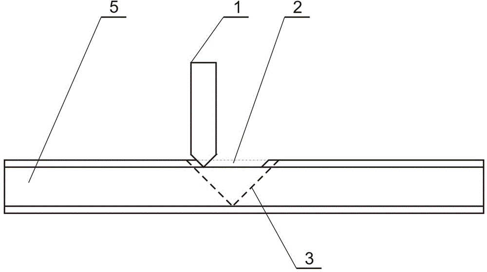
[0011] refer to figure 1 , figure 2 , the stainless steel composite board 5 is clamped on a planer equipped with a milling power head, a V-shaped planer 1 with a large rake angle is selected, and a flat groove 2 is planed on the surface of the stainless steel composite board 5, and the position of the flat groove 2 is centered on the V shaped groove 3, and the width is smaller than the boundary of the V-shaped groove 3, and the depth of the flat groove 2 is to cut off the stainless steel surface until the composite layer is exposed;

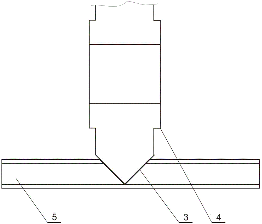
[0012] Start the milling power head, implement milling, and implement milling in the flat groove 2 with a V-shaped horizontal milling cutter until the V-shaped groove 5 on the stainless steel composite plate is formed.

[0013] The present invention uses planing technology to plan a flat groove on the surface of the stainless steel composite board, and cuts off the stainless steel part to be processed into a V-shaped groove. Due to the use of a...


PUM


Abstract

The invention discloses a method for processing a V-shaped groove of a stainless steel composite plate. The method comprises planing processing and milling processing. The planing processing means the operation of cutting a flat groove on the surface of the tainless steel composite plate, the position of the flat groove is at the middle of the V-shaped groove, the width of the flat groove is smaller than the edge of the V-shaped groove, and the depth of the flat groove is obtained by cutting off a stainless steel surface layer until a composite layer is exposed. The milling processing means the operation of utilizing a V-shaped milling cutter to perform milling in the flat groove until the V-shaped groove in the stainless steel composite plate is formed. According to the method, a processing mode of first performing planing and then performing milling is adopted, the V-shaped groove is processed in the stainless steel composite plate by utilizing the characteristics of small planing resistance and high milling forming accuracy, and the method has the advantages of easiness in cutting, high working efficiency and good forming accuracy.

Description

technical field [0001] The invention relates to the technical field of metal cutting, in particular to a method for processing a V-shaped groove of a stainless steel composite plate. Background technique [0002] With the rapid development of decorative materials, various composite decorative panels abound, and stainless steel composite panels are one of them. Ordinary stainless steel composite panels are composed of PVC panels or stainless steel honeycomb panels sandwiched between two layers of stainless steel panels. Stainless steel composite panels are used in At the same time, it is necessary to process a V-shaped groove on a layer of stainless steel panels and intermediate interlayer plates. In order to ensure the accuracy of the geometric shape of the V-shaped groove, forming end mills or horizontal milling cutters are often used for cutting. During the cutting process, cutting is difficult and The work efficiency is low, especially because of the relative concentr...

Claims


Application Information

Patent Timeline
Patent Type & Authority Applications(China)
IPC IPC(8): B23P13/02
CPCB23P13/02
Inventor 周开霖
Owner 上海斯诺博建筑科技有限公司
Why Eureka
Try Eureka