Lubricating oil composition
A technology of lubricating oil composition and synthetic oil, applied in the directions of lubricating composition, petroleum industry, additives, etc., can solve the problems of increased wear and the like, and achieve the effects of high fuel consumption performance, long oil change interval, and long piston cleanliness
Inactive Publication Date: 2015-08-05
IDEMITSU KOSAN CO LTD +1
View PDF10 Cites 11 Cited by
- Summary
- Abstract
- Description
- Claims
- Application Information
AI Technical Summary
Problems solved by technology
However, if the HTHS viscosity is too low, the amount of wear will increase
Method used
View moreImage
Smart ImageViewing Examples

Examples
Embodiment
[0134] Hereinafter, the present invention will be further described in detail through examples. The present invention is not limited to the following examples.
Login to View More PUM
| Property | Measurement | Unit |
|---|---|---|
| shear viscosity | aaaaa | aaaaa |
| viscosity index | aaaaa | aaaaa |
| viscosity index | aaaaa | aaaaa |
Abstract
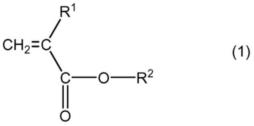
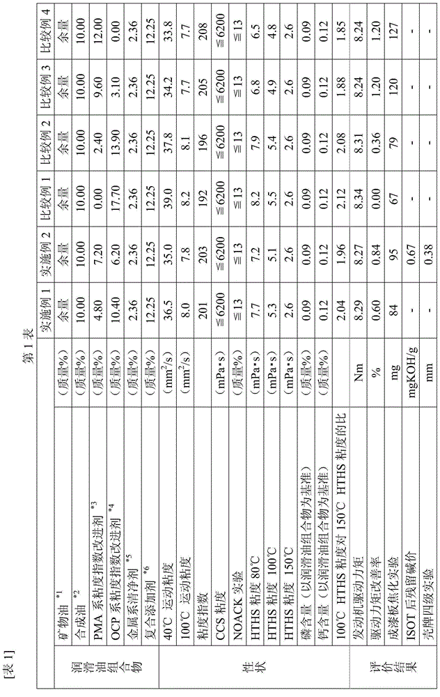
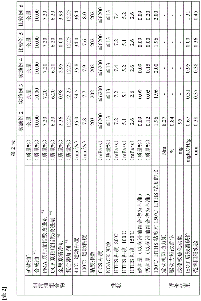
[Problem] To provide a lubricating oil composition capable of attaining high-level fuel efficiency, durability and piston detergency in internal-combustion engines. [Means for Resolution] The lubricating oil composition according to the present invention contains a viscosity index improver and a metallic detergent in at least one base oil selected from mineral oils and synthetic oils therein, wherein the viscosity index improver contains a polymethacrylate viscosity index improver and an olefin copolymer viscosity index improver, the polymethacrylate viscosity index improver is contained in an amount of from 3.0% by mass to 9.5% by mass based on the total amount of the lubricating oil composition, the metallic detergent is at least one selected from calcium sulfonate, calcium phenate and calcium salicylate, the calcium amount derived from the metallic detergent is from 500 ppm to 1500 ppm based on the total amount of the lubricating oil composition, the high-temperature high-shear viscosity at 150°C of the lubricating oil composition is 2.6 mPa·s or more, the high-temperature high-shear viscosity at 80°C of the lubricating oil composition is 7.8 mPa·s or less, and the ratio of the high-temperature high-shear viscosity at 100°C of the lubricating oil composition to the high-temperature high-shear viscosity at 150°C thereof is 2.05 or less.
Description
technical field [0001] The present invention relates to a lubricating oil composition, which is applied to internal combustion engines such as diesel engines, gasoline engines, gas engines, and hybrid vehicle engines. Background technique [0002] Currently, measures to address environmental issues such as global warming or the depletion of petroleum resources are desired by society due to the improvement of environmental awareness on a global scale. In the field related to automobiles, exhaust gas control, reduction in fuel consumption of automobiles, and the like are more desired. [0003] Exhaust gas filters such as diesel particulate filters, gasoline particulate filters, and three-way Exhaust gas post-treatment devices such as catalysts and oxidation catalysts. [0004] In this case, it is known that metal components are mixed into the exhaust gas flow and deposited in the aftertreatment device, reducing the removal efficiency. Therefore, it has been proposed to redu...
Claims
Login to View More Application Information
Patent Timeline
 Patent Type & Authority Applications(China)
IPC IPC(8): C10M169/04C10M177/00C10N30/02C10N40/25
CPCC10N2240/104C10M2223/045C10M169/048C10N2230/50C10M2207/026C10N2230/04C10M2205/04C10M2209/084C10N2230/10C10M2205/022C10N2230/74C10N2230/02C10N2230/42C10N2230/54C10N2230/06C10M2215/28C10N2240/102C10N2230/68C10M2215/221C10M161/00C10N2240/10C10M2205/026C10N2030/04C10N2030/02C10N2030/10C10N2030/50C10N2030/42C10N2030/54C10N2030/68C10N2030/74C10N2030/06C10N2040/252C10N2040/255C10N2040/25C10M2205/06C10M2205/028C10N2020/04C10M2207/027C10N2010/04C10M2207/028C10M2207/144C10M2207/262C10M2219/044C10M2219/046
Inventor 伊藤耕辉藤本公介山下实
Owner IDEMITSU KOSAN CO LTD
Features
- R&D
- Intellectual Property
- Life Sciences
- Materials
- Tech Scout
- Unparalleled Data Quality
- Higher Quality Content
- 60% Fewer Hallucinations
Learn More Browse by: Latest US Patents, China's latest patents, Technical Efficacy Thesaurus, Application Domain, Technology Topic, Popular Technical Reports.
© 2025 PatSnap. All rights reserved.Legal|Privacy policy|Modern Slavery Act Transparency Statement|Sitemap|About US| Contact US: help@patsnap.com