Double-camera machine vision positioning method of surface mounted component

A surface mount component, machine vision technology, applied in the electrical field

Active Publication Date: 2015-08-05
SHANGHAI RO INTELLIGENT SYST
View PDF6 Cites 11 Cited by
  • Summary
  • Abstract
  • Description
  • Claims
  • Application Information

AI Technical Summary

Problems solved by technology

[0003] The object of the present invention is to provide a dual-camera machine vision positioning method for surface mount components, the dual-camera machine vision positioning method for such surface mount components The method is to solve the technical problems of lack of precision and errors in the visual positioning technology that obtains the position through template image analysis in the prior art

Method used


Image

  • Double-camera machine vision positioning method of surface mounted component

Examples


Embodiment 1

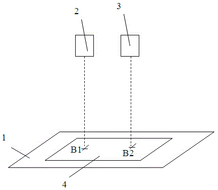
[0024] like figure 1 As shown, a dual-camera machine vision positioning method for surface mount components of the present invention includes a process of using cameras to collect and analyze images of surface mount components, wherein, in the described method of using cameras to collect and analyze surface mount components In the process of the image, a pallet platform 1 that can translate and rotate in the horizontal direction is set, a first camera 2 and a second camera 3 are set above the pallet platform 1, and the first The camera 2 and the second camera 3 are all arranged on a guide rail (not shown in the figure), and a driving mechanism (not shown in the figure) is arranged between the first camera 2 and the second camera 3 and the guide rail, and the The control end of the driving mechanism is connected to a servo controller (not shown in the figure), an image data transmission channel is set between the first camera 2 and the second camera 3 and a computer (not shown ...


PUM


Abstract

A double-camera machine vision positioning method of a surface mounted component includes a process of using two cameras to collect images of the surface mounted component, a tray platform which is translatable and rotatable in a horizontal direction, two cameras are arranged above the tray platform, an image data transmission channel is arranged between the cameras and a computer, a calibration step is carried out at first, and then a step of positioning a workpiece to be machined is carried out. The two cameras are used to shoot images, and a series of positioning motion data are collected, thereby obtaining a coordinate system of positioning by two points collected by vision, two points on the workpiece which have a certain distance are sampled, the measuring cardinal number is enlarged by one order of magnitude, errors of the images can almost be ignored, dependency on shapes of feature points and a vision algorithm can be avoided, and thus the double-camera machine vision positioning method of the surface mounted component has a wider range of application, and is higher in precision.

Description

Technical field: [0001] The invention relates to the field of electricity, in particular to the surface mounting technology of electronic components, in particular to a dual-camera machine vision positioning method for surface mounting components. Background technique: [0002] In the surface mount technology industry, due to the high precision of the products and the complex and changeable workpiece conditions, it is impossible to produce accurately and at high speed with traditional positioning methods. In the prior art, the visual positioning method is used to improve the positioning efficiency of surface mount components on the processing tray platform. However, the existing visual positioning technology obtains the position through the analysis of the template image, specifically, a vector graphic with a certain degree of recognition on the target workpiece is used to find out its angle and position through visual calculation. This method is not accurate enough, especi...

Claims


Application Information

Patent Timeline
Patent Type & Authority Applications(China)
IPC IPC(8): G01B11/00
Inventor 吕德云王德民
Owner SHANGHAI RO INTELLIGENT SYST
Why Eureka
Try Eureka