
Hartmann detection device for continuous sampling

A detection device and quality technology, which is applied in the field of continuous sampling Hartmann detection devices, can solve the problems of indirect detection results, poor measurement flexibility, and non-adjustable size, etc.

Inactive Publication Date: 2007-07-11
SHANGHAI INST OF OPTICS & FINE MECHANICS CHINESE ACAD OF SCI
View PDF5 Cites 0 Cited by
  • Summary
  • Abstract
  • Description
  • Claims
  • Application Information

AI Technical Summary

Problems solved by technology

[0004] 1. Unable to measure local error
Because the small holes distributed on the diaphragm are discontinuous, some areas on the surface of the lens to be inspected cannot be sampled.
[0005] 2. Discontinuous sampling brings errors to the calculation
[0006] 3. The size of the small hole on the Hartmann diaphragm cannot be adjusted, and the measurement flexibility is poor
Due to the complexity of the large-aperture collimator, it is almost impossible to replace the detection light source, so it cannot be detected with the working wavelength of the inspected lens, resulting in indirect detection results.

Method used


Image

  • Hartmann detection device for continuous sampling
  • Hartmann detection device for continuous sampling
  • Hartmann detection device for continuous sampling

Examples


Embodiment Construction

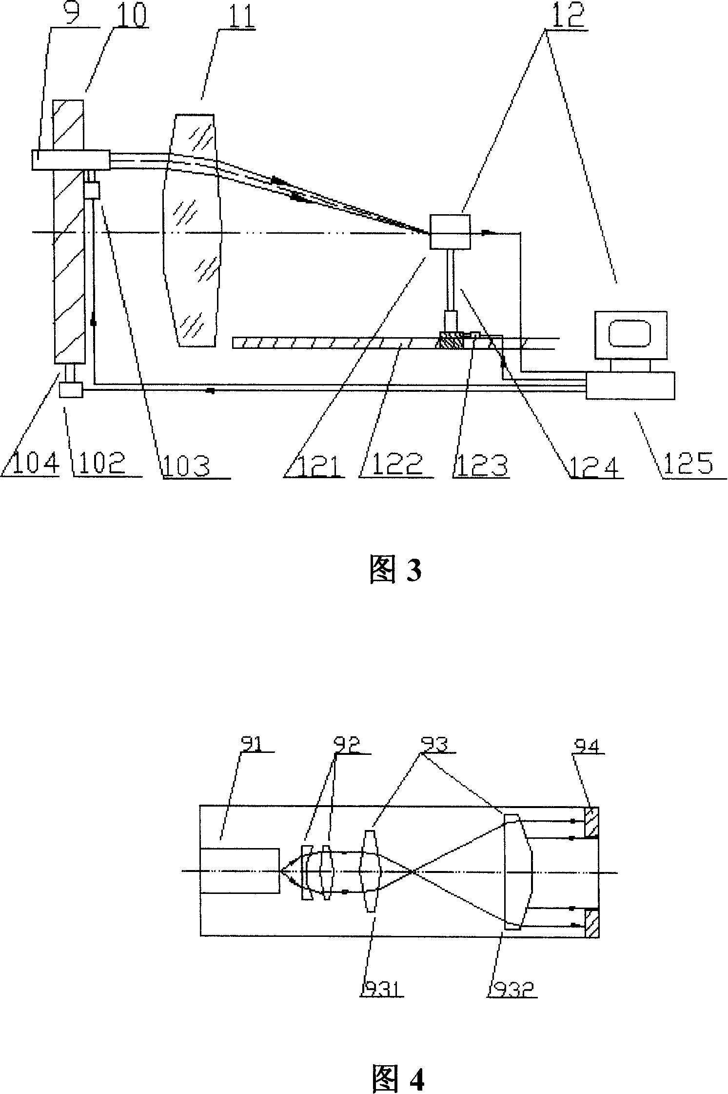
[0036]Please refer to FIG. 3 first. FIG. 3 is a schematic structural diagram of a specific embodiment of the continuous sampling Hartmann detection device of the present invention. As can be seen from the figure, the present invention is composed of an illumination system 9, a light beam scanning mechanism 10, an inspected lens 11, an image receiving system 12, and system control and data processing software. The illumination system 9 is fixed on the one-dimensional electric adjustment frame 103 in the beam scanning mechanism 10 , and the one-dimensional electric adjustment frame 103 is controlled by a computer 125 . The beam scanning mechanism 10 is installed on the bracket 104, and one side of the bracket 104 is fixed with a first stepping motor 102 controlled by a computer 125, and the beam scanning mechanism 10 can be driven by the first stepping motor 102 around the The optical axis of the lens 11 rotates; the inspected lens 11 has a converging effect on the light beam. ...


PUM


Abstract

It is a Hageman detecting apparatus used to continuous sample in lens optics quality measurement, which comprises the light system, beam scanning structure, measured lens, image receiving system and system control and data process software. It is characterized by the following: the said lighting system is calibration light source with beam diameter adjustable; the said beam scanning structure comprises image screen, first step motor, one dimensional motor adjusting rack and support rack; the said image receiving system comprise CCD cameral, guiding rail, second step motor, rack and computer, wherein, the computer is connected with first step motor, second step motor, third step motor and CCD cameral through signal line.

Description

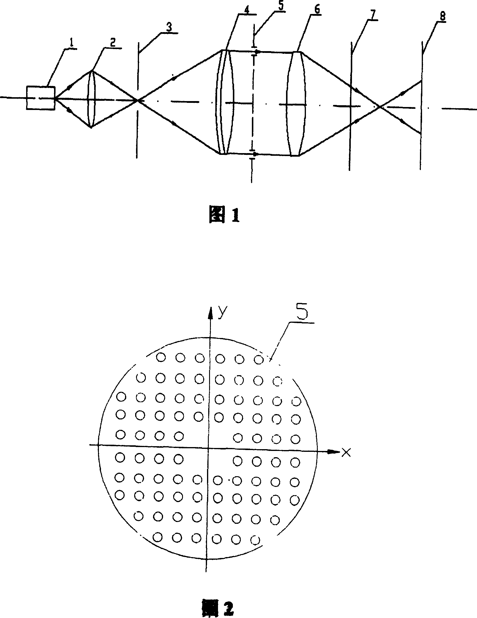
technical field [0001] The invention relates to the detection of the quality of optical components, in particular to a continuous sampling Hartmann detection device. Background technique [0002] The Hartmann detection method is a quantitative detection method to determine the quality of the inspected lens through the concentric degree of the converging beam of the inspected lens. Its main component is an opaque Hartmann diaphragm, which uses small holes at different positions on the diaphragm to divide the detection beam, so as to obtain the difference in the converging point position of the sub-beams irradiated on different areas of the inspected lens. The structure of the traditional Hartmann detection device is shown in Figure 1. The light emitted by the light source 1 illuminates the aperture diaphragm 3 through the condenser lens 2, thereby obtaining a point light source; the aperture aperture 3 is located at the front focus of the collimator 4, and the The light beam...

Claims


Application Information

Patent Timeline
Patent Type & Authority Patents(China)
IPC IPC(8): G01M11/02G01M11/00
Inventor 黄惠杰闫岩刘丹任冰强赵永凯黄立华张维新
Owner SHANGHAI INST OF OPTICS & FINE MECHANICS CHINESE ACAD OF SCI
Learn More