
A bidirectional sampling circuit, sampling method and testing method thereof

A sampling circuit and bidirectional current technology, applied in the electronic field, can solve the problems of large circuit area and power consumption, high-precision voltage reference calibration and high test cost, achieve low hardware cost, optimize test cost, and improve overall performance.

Active Publication Date: 2021-03-16
SHANGHAI ANALOGY SEMICON TECH LTD
View PDF9 Cites 0 Cited by
  • Summary
  • Abstract
  • Description
  • Claims
  • Application Information

AI Technical Summary

Problems solved by technology

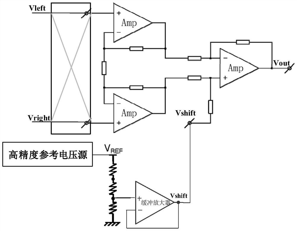
[0006] However, in the traditional current detection circuit, due to the use of three chopper amplifiers Amp and buffer amplifier Buffer, the circuit area and power consumption are large, and the calibration and testing costs of the high-precision voltage reference are also high

Method used


Image

  • A bidirectional sampling circuit, sampling method and testing method thereof
  • A bidirectional sampling circuit, sampling method and testing method thereof
  • A bidirectional sampling circuit, sampling method and testing method thereof

Examples


Embodiment 1

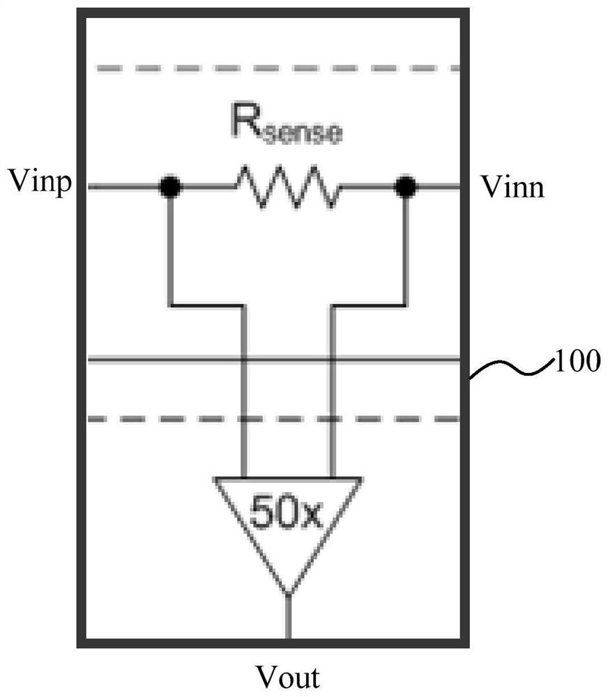
[0050] refer to figure 2 As shown, the present application discloses a bidirectional sampling circuit 100, which can detect the current flowing bidirectionally between the first input terminal Vinp and the second input terminal Vinn, and indirect sampling between the first input terminal Vinp and the second input terminal Vinn The resistor Rsense outputs the sampling voltage Vout.

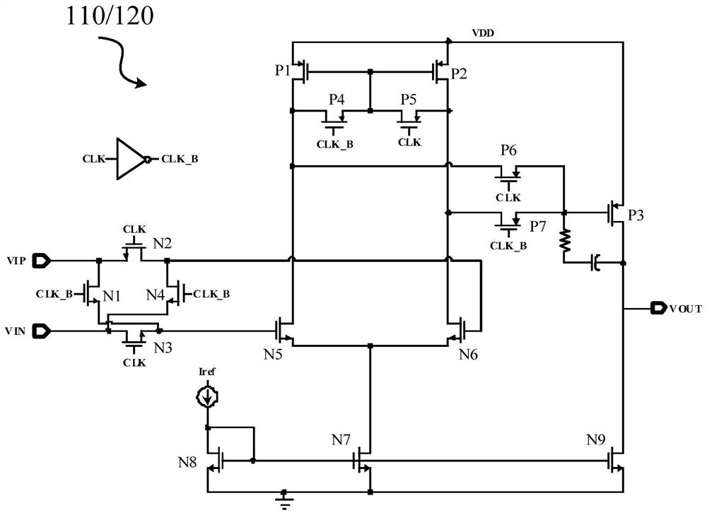
[0051] refer to image 3 As shown, the bidirectional sampling circuit in this embodiment includes a first amplifier 110 and a second amplifier 120, first to fourth resistors R1, R2, R3, R4, first to tenth switches S1, S2, S3, S4 , S5, S6, S7, S8, S9, S10. Wherein, the first to tenth switches S1 , S2 , S3 , S4 , S5 , S6 , S7 , S8 , S9 , and S10 are switching transistors, such as MOS transistors, which are opened or closed by controlling the gates of the MOS transistors.

[0052] One end of the first resistor R1 is used as the first input terminal Vinp of the bidirectional sampling circuit 100, c...

Embodiment 2

[0068] continue to refer image 3 As shown, the application also discloses a two-way sampling method, including:

[0069] When the current of the sampled circuit flows from the input end to the output end, that is, when the current method of the bidirectional sampling circuit 100 is from the first input end Vinp to the second input end Vinn, the first, fourth, sixth, and seventh , the tenth switch S1, S4, S6, S7, S10, open the second, third, fifth, eighth, ninth switch S2, S3, S5, S7, S9;

[0070] The output voltage of the bidirectional sampling circuit is:

[0071]

[0072] Wherein, Gain_A is the gain of the first amplifier 110, Gain_B is the gain of the second amplifier 120, Vos_A is the offset voltage (offset) of the first amplifier 110, Vos_B is the offset voltage of the second amplifier 120 (offfect), Vinp is the voltage of the first input terminal (the input terminal of the sampled circuit), and Vinn is the voltage of the second input terminal (the output terminal o...

Embodiment 3

[0075] continue to refer image 3As shown, the application also discloses a two-way sampling method, including:

[0076] When the current of the sampled circuit flows from the output terminal to the input terminal, that is, the circuit direction of the bidirectional sampling circuit 100 is from the second input terminal Vinn to the first input terminal Vinp, the first, fourth, sixth, and seventh , the tenth switch S1, S4, S6, S7, S10, closing the second, third, fifth, eighth, ninth switch S2, S3, S5, S7, S9;

[0077] The output voltage of the bidirectional sampling circuit is:

[0078]

[0079] Wherein, Gain_A is the gain of the first amplifier 110, Gain_B is the gain of the second amplifier 120, Vos_A is the offset voltage (offset) of the first amplifier 110, Vos_B is the offset voltage of the second amplifier 120 (offfect), Vinp is the voltage of the first input terminal (the input terminal of the sampled circuit), and Vinn is the voltage of the second input terminal (t...


PUM


Abstract

The invention relates to a bidirectional sampling circuit, a sampling method and a testing method. One end of a first resistor is connected with the input end of a sampled circuit, and the other end of the first resistor is connected with the negative input end of a first amplifier through a second switch and is connected with the positive input end of a second amplifier and one end of a third resistor through sixth switches; one end of a second resistor is connected with the output end of the sampled circuit, and the other end of the second resistor is connected with the positive input end ofthe first amplifier through a third switch and is connected with the negative input end of the second amplifier and one end of a fourth resistor through seventh switches; the other end of the third resistor is connected with the negative input end of the first amplifier through a first switch, and the output end of the first amplifier is connected to the output end of the bidirectional sampling circuit through a ninth switch; the other end of the fourth resistor is connected with the negative input end of the second amplifier and the output end of the second amplifier through eighth switchesand is connected to the output end of the bidirectional sampling circuit through a tenth switch; and offset voltage is connected with the positive input end of the first amplifier through a fourth switch and is connected with the positive input end of the second amplifier through a fifth switch.

Description

technical field [0001] The invention belongs to the field of electronic technology, such as being applied to various batteries, DCDC, fast charging, or the detection and measurement of micro current and power, and particularly relates to a bidirectional sampling circuit, a sampling method and a bidirectional sampling method for bidirectional charging and discharging of batteries in a dual battery system. Test method, dual battery management system. Background technique [0002] Hybrid cars use a high-voltage 48V battery alongside a standard 12V car battery. The efficient and highly reliable dual battery management system solution has become the core power supply system of the hybrid electric vehicle electronic system. At present, the dual battery management system has all-analog solutions, all-digital solutions and mixed analog-digital solutions. In order to improve the overall performance, safety and reliability of the lithium battery system, the charge and discharge accu...

Claims


Application Information

Patent Timeline
Patent Type & Authority Patents(China)
IPC IPC(8): G01R19/00
CPCG01R19/00
Inventor 邹思佳张俊张泽飞
Owner SHANGHAI ANALOGY SEMICON TECH LTD
Learn More