Device and method for testing peak value optical power of continuous narrow pulse width laser

A test device and test method technology, which is applied in the direction of using electric radiation detectors for photometry, etc., can solve the problems of complex circuit device design, impact test, non-pulse optical power test, etc., so as to improve independence and stability, reduce The effect of cost input and system volume reduction

Inactive Publication Date: 2015-08-05
CHINA ELECTRONIS TECH INSTR CO LTD
View PDF6 Cites 11 Cited by
  • Summary
  • Abstract
  • Description
  • Claims
  • Application Information

AI Technical Summary

Problems solved by technology

[0008] (1) The test device has an external input trigger interface, and the optical power acquisition is synchronized through the external trigger mode, which greatly increases the condition requirements for the measurement signal and increases the complexity and uncertainty of the measurement;
[0009] (2) After the external trigger condition is added, the work of the internal peak hold circuit also uses the external trigger as the trigger switch of the peak hold circuit. At the same time, it is necessary to use a fast switch to discharge the held peak voltage so as not to affect the subsequent test, thus causing The design of the circuit device is complex, and the condition dependence on the external measurement source is high;
[0010] (3) Most optical power test devices can only test continuous optical power, but cannot test pulsed optical power

Method used


Image

  • Device and method for testing peak value optical power of continuous narrow pulse width laser
  • Device and method for testing peak value optical power of continuous narrow pulse width laser
  • Device and method for testing peak value optical power of continuous narrow pulse width laser

Examples


Embodiment Construction

[0035] combined with Figures 1 to 2 The specific embodiment of the present invention is described further:

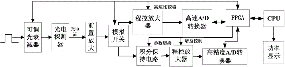
[0036] A test device for the peak optical power of a continuous narrow pulse width laser, including a controllable attenuator, a photoelectric conversion acquisition circuit and a central processing unit. The acquisition circuit, the photoelectric conversion acquisition circuit is connected to the central processing unit through a field programmable gate array FPGA, and the central processing unit is connected to a display module;

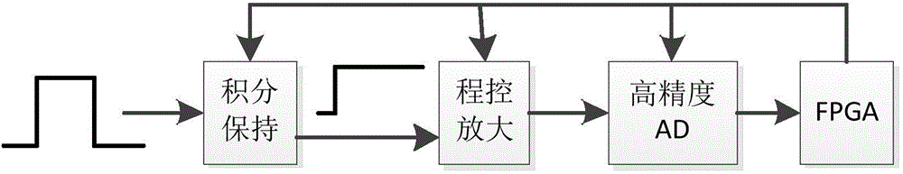
[0037] The photoelectric conversion acquisition circuit includes a photoelectric conversion detector and two parallel pulse width frequency test channels and an integral hold channel, the initial ends of the pulse width frequency test channel and the integral hold channel are connected with analog switches for switching, and the terminals are respectively passed through The field programmable gate array FPGA is connected to the central pro...


PUM


Abstract

The invention discloses a device and method for testing the peak value optical power of a continuous narrow pulse width laser. The device comprises a controllable attenuator, a photoelectric conversion sampling circuit and a central processor. The controllable attenuator is connected with an optical fiber input interface of a pulse optical source under test. The controllable attenuator is connected with the photoelectric conversion sampling circuit. The photoelectric conversion sampling circuit is connected with the central processor through a field programmable gate array (FPGA). The central processor is connected with a display module. Through the acquisition circuit designed by high-speed optical pulse conversion technology, high-speed pulse signal frequency and pulse width measuring technology, continuous pulse optical integration maintenance technology and range automatic shifting technology, the design of the device for testing the pulse optical power is achieved, the stand-alone device and method can be used for completing the test of the continuous pulse optical power, the problem of difficulty in instrumentation due to too many related links is overcome, the cost input and the system size are thus reduced, the operating procedure is simplified, and the device and method are highly versatile.

Description

technical field [0001] The invention relates to a test device and a test method for the peak optical power of a continuous narrow pulse width laser. Background technique [0002] Traditionally, the laser peak power is defined as the ratio of the laser pulse energy to the half-width of the laser pulse. When the repetition frequency is low or the pulse width is wide, the half-width H of the laser pulse waveform can be measured first with a waveform detector and an oscilloscope, and then the energy E of the laser pulse can be measured with a laser energy meter. then press P p =E / H Calculate the laser peak power. When the repetition frequency is high or the pulse width is narrow, since the laser pulse energy cannot be directly measured, the laser pulse frequency f and the laser pulse waveform half-width H can be measured with a waveform detector and an oscilloscope first, and then the laser power meter can be used to measure the laser pulse energy. Average power P av . Then...

Claims


Application Information

Patent Timeline
Patent Type & Authority Applications(China)
IPC IPC(8): G01J1/42
Inventor 刘磊闫继送孙强吴寅初韩顺利
Owner CHINA ELECTRONIS TECH INSTR CO LTD
Why Eureka
Try Eureka