Sample injection tube

A sampling tube and sample technology, applied in the field of sampling tubes, can solve problems such as cable or trachea falling off, installation difficulty, trachea extrusion, etc., and achieve the effects of facilitating manufacturing and assembly, reducing processing difficulty, and reducing processing costs.

Active Publication Date: 2015-08-05
ウーハン ジョンケ ニウジン マグネティック レゾナンス テクノロジー カンパニー リミテッド
View PDF5 Cites 0 Cited by
  • Summary
  • Abstract
  • Description
  • Claims
  • Application Information

AI Technical Summary

Problems solved by technology

[0004] (1) The fixed plate above the pipeline realizes the fixation of the sample tube and the connection of the gas pipe and cable connector at the same time, but the position of the fixed plate often needs to be adjusted during the installation of the pipeline, and the gas pipe and cables connected below it cause the fixed plate to be distorted. Difficult to adjust and install;
[0005] (2) Cables and air pipes are wrapped around the pipes. When adjusting the position of the fixed disk, the positions of the cables and air pipes need to be readjusted. It is easy to cause problems such as air pipes being squeezed, cables or air pipes falling off, and installation is more difficult;
[0006] (3) There is no obvious mark on the position of the fixed plate. When the sample tube is folded or re-adjusted, repeated adjustments and tests are required to determine the best position;
[0007] (4) When realizing the rotation, use one suspension gas and one rotation gas respectively, the suspension gas is vertically upward, so that the tested sample is in a suspended state, and the rotation gas is in the horizontal circumferential direction, so that the tested sample is rotated, this design requires at least 3 The input of the air flow, the design of the pneumatic components is very complicated, and the precision is high, which increases the manufacturing cost of the sampling tube

Method used


Image

  • Sample injection tube
  • Sample injection tube
  • Sample injection tube

Examples


Embodiment Construction

[0027] In order to make the object, technical solution and advantages of the present invention clearer, the present invention will be further described in detail below in conjunction with the accompanying drawings and embodiments. It should be understood that the specific embodiments described here are only used to explain the present invention, not to limit the present invention. In addition, the technical features involved in the various embodiments of the present invention described below can be combined with each other as long as they do not constitute a conflict with each other.

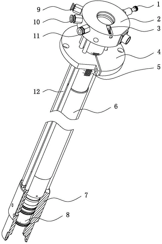
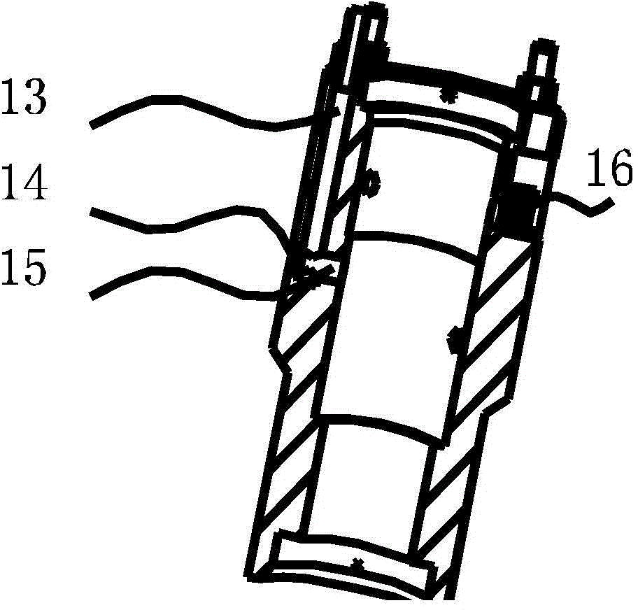
[0028] Such as figure 1 As shown, the sampling tube proposed by the present invention consists of a support seat 7, a support ring 8, a pipeline 6, an adjustment flange 4 and a joint mounting seat 2, a state monitoring sensor 3 and a test sensor 16, a sample gas flow channel 9, a rotating gas flow channel 10. It is composed of components such as the sample air flow channel 11 and the exhaust ch...


PUM


Abstract

The invention discloses a sample injection tube which includes a pipeline for injecting or discharging a to-be-test sample, a mounting base arranged on an upper end of the pipeline and a supporting ring arranged on the bottom end of the pipeline. A supporting base sleeves externally the supporting ring. A plurality of gas channels are formed between the mounting base and the supporting base. A plurality of L-shaped channels are formed in the mounting base, wherein one ends of the L-shaped channels are communicated with the gas channels and the other ends of the L-shaped channels are communicated with the supporting ring. Action on the to-be-test sample is achieved through air pores formed on the supporting ring. According to the invention, the structures of the supporting base and the supporting ring in the sample injection tube are optimized so that the functions of suspension and rotation of the sample are achieved by one gas flow, thereby reducing processing difficult and processing precision, and furthermore reducing processing cost. The sample injection tube is convenient to manufacture and assemble.

Description

technical field [0001] The invention belongs to the field of nuclear magnetic resonance spectrometers, and more specifically relates to a sample injection tube for a tested sample to enter and exit the nuclear magnetic resonance spectrometer. Background technique [0002] The sampling tube is an indispensable part of the NMR spectrometer when analyzing the tested sample. It is the inlet and outlet channel of the tested sample. The sampling tube is a hollow tubular structural member, which is installed vertically in the NMR spectrometer. Since the sample to be tested has a certain weight and is placed at the bottom of the sampling tube, in order to slowly put the sample into the sampling tube, it is necessary to provide an upward airflow with a continuously decreasing flow rate, so that the sample is The sample to be measured slowly descends into the injection tube under the support of the airflow. On the contrary, when the sample needs to be ejected from the injection tube, ...

Claims


Application Information

Patent Timeline
Patent Type & Authority Applications(China)
IPC IPC(8): G01N1/02
Inventor 杨中胤
Owner ウーハン ジョンケ ニウジン マグネティック レゾナンス テクノロジー カンパニー リミテッド
Why Eureka
Try Eureka