Acidic gas treating process and system

A treatment process and acid gas technology, applied in the field of acid gas treatment process and system, can solve the problems of inability to produce valuable oleum, easy deterioration of sodium sulfide, difficult to popularize, etc., to improve mass transfer and reaction efficiency, reactor The effect of reducing the scale and ensuring long-term operation

Active Publication Date: 2015-08-12
CHINA PETROLEUM & CHEM CORP +1
View PDF8 Cites 3 Cited by
  • Summary
  • Abstract
  • Description
  • Claims
  • Application Information

AI Technical Summary

Problems solved by technology

[0004] The two-stage Claus + tail gas hydrogenation reduction + solvent absorption technology has mature technology, stable operation, and stable product sulfur quality. However, due to the long process and large investment, the Claus process can only deal with high-concentration acid gases. 2 When the S volume fraction is less than 20%, the device is not easy to operate
This process can only produce 98% industrial sulfuric acid, but cannot produce oleum with higher value. At the same time, due to the difficulty in the transportation and storage of sulfuric acid, the stable market demand near the refinery is an important factor limiting its development.
[0009] CN1836767A discloses a treatment method for sour gas in refineries, utilizing sour gas as the fuel for shaft kilns in cement plants, when the sour gas is burned in the kiln, the H 2 S component reacts chemically with cement material to generate CaSO 4 , other harmful components are also sintered and transformed, which fundamentally solves the problem of acid gas treatment. At the same time, acid gas is used as a gas fuel to make the cement plant energy-saving fuel and achieve the dual purposes of environmental protection and fuel resolution. However, this The method has certain limitations and is not easy to promote
However, the sodium sulfide product of this process is prone to deterioration and is not easy to store

Method used


Image

  • Acidic gas treating process and system
  • Acidic gas treating process and system

Examples


Embodiment 1

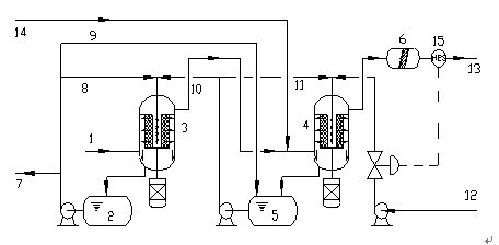
[0055] use as figure 1 The process device shown uses acid gas and NaOH solution as raw materials to carry out the reaction. CO in acid gas 2 The volume fraction is 7%, H 2 The volume fraction of S is 92%, and the volume fraction of hydrocarbons is 1%. The mass concentration of NaOH solution is 35%.

[0056]In the embodiment of the present invention, the primary reactor and the secondary reactor adopt rotary bed reactors, and the reaction temperature in the primary rotary bed reactor and the secondary rotary bed reactor is 85°C. The temperature of the primary intermediate tank and the secondary intermediate tank is 90°C. The rotational speed of the rotating bed of the first-stage rotating bed reactor and the second-stage rotating bed reactor is 1500 rpm. The residence time of the reaction materials in the primary rotary bed reactor and the secondary rotary bed reactor is 10 seconds.

[0057] In the process of the present invention, in step (1), the volume flow ratio of th...


PUM


Abstract

The invention discloses an acidic gas treating process and system. The acidic gas treating process employs a two-stage gas-liquid two-phase countercurrent absorption reaction and uses a NaOH solution as an absorption liquid to treat acidic gas so as to produce NaHS. According to the process, a primary liquid reaction product and a secondary liquid reaction product are cyclically used, and the primary liquid reaction product is circulated to a secondary intermediate tank and used as a diluent. The acidic gas treating system adopts a rotating bed reactor as a gas-liquid reactor; CO2 in the acidic gas reacts with NaOH to produce nanometer Na2CO3 crystal, so obstruction of a pipeline by the Na2CO3 crystal during fluid conveying is prevented. The acidic gas treating process provided by the invention is simple and can achieve the dual objectives of purification of acidic gas and reclamation of pollutants; and the acidic gas treating system has the advantages of small scale, low energy consumption and low proneness to obstruction.

Description

technical field [0001] The invention relates to an acid gas treatment process and system, which belongs to the field of acid gas purification, and in particular to a treatment method and device suitable for the purification of sulfur-containing hydrogen acid acid gas and the recycling of pollutants. Background technique [0002] Refinery acid gas mainly comes from sour water stripping, circulating hydrogen desulfurization, dry gas desulfurization and other devices. The acid gas mainly contains H 2 S, CO 2 . At present, the acid gas in most small refineries basically adopts the treatment method of post-combustion emission. On the one hand, this method causes a waste of resources, on the other hand, it brings huge pressure to environmental protection and affects the development space of enterprises. In order to protect the environment and ensure the full utilization of resources, it is imperative to recycle the acid gas from small refineries. [0003] The treatment of acid...

Claims


Application Information

Patent Timeline
Patent Type & Authority Applications(China)
IPC IPC(8): B01D53/78B01D53/52C01B17/32
Inventor 李鹏齐慧敏彭德强王璐瑶孟凡飞陈建兵陈新
Owner CHINA PETROLEUM & CHEM CORP
Why Eureka
Try Eureka