Ladle automatic drainage device

A ladle and automatic technology, applied in the direction of casting melt container, metal processing equipment, casting equipment, etc., can solve the problems of not being able to form a complete arc-shaped sand dune, the change of the performance of the drainage sand, and the super-long refining waiting time, etc., to achieve Improve the automatic pouring rate, large capacity, and good fluidity

Active Publication Date: 2015-08-12
XIXIA XINYUE METALLURGICAL MATERIAL DEV CO LTD
View PDF7 Cites 14 Cited by
  • Summary
  • Abstract
  • Description
  • Claims
  • Application Information

AI Technical Summary

Problems solved by technology

[0004] Ⅰ: The nozzle of the ladle is not cleaned up, and there is steel slag remaining in it. After sand filling, the residual steel slag and the drainage sand are mixed, and are bonded together by the heating of molten steel, blocking the nozzle, resulting in drainage failure;
[0005] Ⅱ: When the drainage sand is filled with sand, a complete arc-shaped dune cannot be formed, or the arc-shaped dune is damaged by factors such as alloy injection, resulting in drainage failure;
[0006] Ⅲ: No pipeline introductio

Method used


Image

  • Ladle automatic drainage device
  • Ladle automatic drainage device

Examples


Embodiment 1

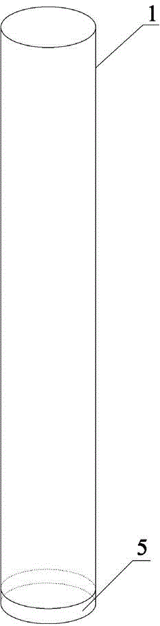
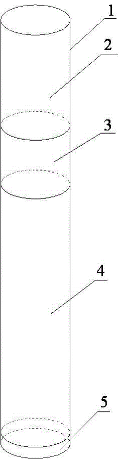
[0034] The ladle automatic drainage device of the present invention includes a cylinder body 1 and drainage materials, the drainage material is a single-layer structure, the cylinder body 1 is made of prefabricated thin-walled steel, and the top of the cylinder body 1 is sealed with prefabricated thin-walled steel, and the The bottom of cylinder body 1 adopts hard low-temperature melting plastic sealing 5.

[0035] Specifically, the drainage material is made of 50.1 parts by weight of chrome sand, 48.5 parts by weight of silica sand, and 1.4 parts by weight of carbon black and / or graphite. Wherein, the particle size of the chromium ore is 20-80 mesh; the particle size of the silica sand is 0.2-2 mm. The preparation method of the above-mentioned drainage material is an existing conventional technology.

[0036] In addition, the size design of the cylinder 1 meets the following requirements: the height of the cylinder 1 is 100-300 mm higher than the bottom of the ladle, and the...

Embodiment 2

[0040] The device structure of this embodiment is the same as that of Embodiment 1, except that the drainage material is made of 94.5 parts by weight of chrome sand, 5.2 parts by weight of silica sand, and 0.3 parts by weight of carbon black and / or graphite. The particle size of the chrome ore is 20-80 mesh. The particle size of the silica sand is 0.2-2 mm.

[0041] The preparation methods of the drainage materials are existing conventional techniques. Its method of use and size requirements are the same as in Embodiment 1, and will not be repeated here.

[0042] The ladle automatic drainage device of this embodiment is used in a B steel factory. The number of counted furnaces is 1012 furnaces; the number of pouring furnaces is 1010 furnaces, the automatic pouring rate is 99.8%, and the waiting time for steel is 2.5 to 3 hours.

Embodiment 3

[0044]The device structure of this embodiment is the same as that of Embodiment 1, except that the drainage material is made of 70.8 parts by weight of chrome sand, 26.2 parts by weight of silica sand, and 3.0 parts by weight of carbon black and / or graphite. The particle size of the chrome ore is 20-80 mesh. The particle size of the silica sand is 0.2-2 mm.

[0045] Wherein, the preparation method of the drainage material follows the existing conventional technology. Its method of use and size requirements are the same as in Embodiment 1, and will not be repeated here.

[0046] The ladle automatic drainage device of this embodiment is used in a steel factory A, and the number of counted furnaces is 1007 furnaces; the number of pouring furnaces is 1007 furnaces, the automatic pouring rate is 100%, and the waiting time for steel exceeds 3 hours.


PUM

PropertyMeasurementUnit
Granularityaaaaaaaaaa

Abstract

The invention provides a ladle automatic drainage device, and belongs to the technical field of a drainage device in iron and steel smelting. The ladle automatic drainage device comprises a cylinder body and drainage material which has a single-layer or multilayer structure. The cylinder body is a prefabricated thin-wall steelwork. The top part of the cylinder body is sealed by adopting prefabricated thin-wall steel. The bottom part of the cylinder body is sealed by adopting hard low temperature melted plastics. The ladle automatic drainage device is novel in structure, easy to operate and high in automatic drainage efficiency so that a non-self-open drainage phenomenon caused by a water port cleaning problem can be completely avoided, in-tube drainage sand is not liable to be affected by damp and is not liable to be polluted by other material in ladle to affect self-open rate, and thus labor force is saved, stability performance is great and use is safe.

Description

technical field [0001] The invention belongs to the technical field of ladle drainage, and in particular relates to an automatic ladle drainage device. Background technique [0002] Ladle drainage is a key technology in iron and steel smelting. The traditional method generally uses the ladle nozzle to fill the drainage sand to realize the drainage and start pouring, which is called the sand filling method. When the drainage sand fails to automatically drain, it is necessary to use an oxygen lance to burn and blow for forced pouring. However, oxygen-rich burning and blowing will increase the oxygen content of molten steel and cause steel degradation. If the burning and blowing time is too long or the burning and blowing fails, will result in a production stoppage. Therefore, the automatic drainage rate is an important indicator to evaluate the quality of drainage agents. The drainage sand with excellent performance and high automatic drainage rate can realize the full prote...

Claims


Application Information

Patent Timeline
IPC IPC(8): B22D41/44
Inventor 程卓
Owner XIXIA XINYUE METALLURGICAL MATERIAL DEV CO LTD
Why Eureka
Try Eureka