Material receiving device and die-cutting machine comprising material receiving device

A material receiving device and material frame technology, which is applied in metal processing and other directions, and can solve the problem of low material receiving efficiency

Active Publication Date: 2015-08-12
广东康派环创科技有限公司
View PDF7 Cites 4 Cited by
  • Summary
  • Abstract
  • Description
  • Claims
  • Application Information

AI Technical Summary

Problems solved by technology

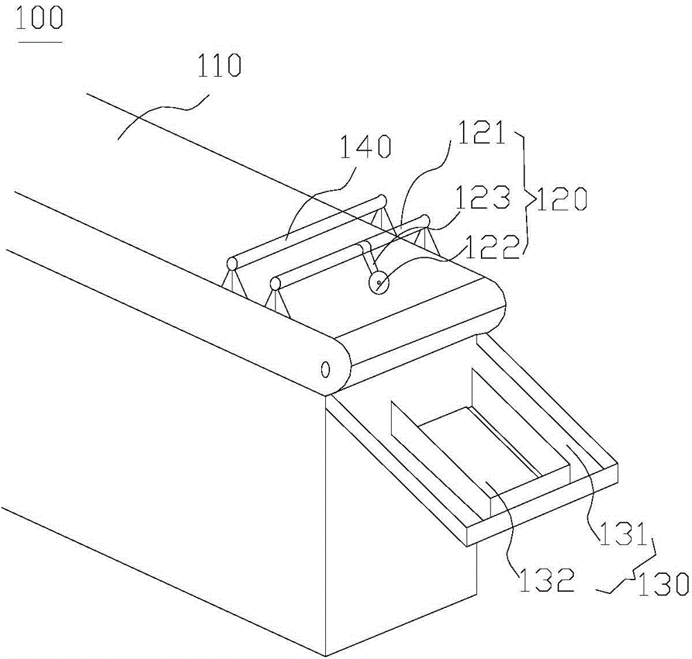
[0004] Based on this, it is necessary to provide a material receiving device with high material receiving efficiency and a die-cutting machine including the material receiving device for the problem of low material receiving efficiency.

Method used


Image

  • Material receiving device and die-cutting machine comprising material receiving device
  • Material receiving device and die-cutting machine comprising material receiving device
  • Material receiving device and die-cutting machine comprising material receiving device

Examples


Embodiment Construction

[0021] In order to facilitate the understanding of the present invention, the present invention will be described more fully below with reference to the associated drawings. Preferred embodiments of the invention are shown in the accompanying drawings. However, the present invention can be embodied in many different forms and is not limited to the embodiments described herein. On the contrary, these embodiments are provided to make the understanding of the disclosure of the present invention more thorough and comprehensive.

[0022] It should be noted that when an element is referred to as being “fixed” to another element, it can be directly on the other element or there can also be an intervening element. When an element is referred to as being "connected to" another element, it can be directly connected to the other element or intervening elements may also be present. The terms "vertical," "horizontal," "left," "right," and similar expressions are used herein for purposes ...


PUM


Abstract

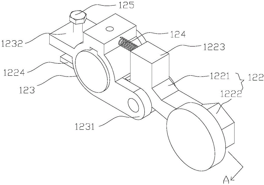
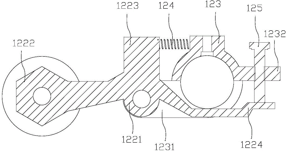
The invention relates to a material receiving device which comprises a transporting mechanism, a guiding assembly and a material receiving assembly, wherein the material receiving assembly is arranged at one end of the transporting mechanism; the guiding assembly comprises a first support and a guiding element; the first support is arranged on the transporting mechanism; one end of the material receiving assembly is arranged close to the transporting mechanism; the guiding element is arranged on the first support and also arranged towards the transporting mechanism, so that the guiding element holds down products when the products transported by the transporting mechanism are positioned between the guiding element and the transporting mechanism; when the material receiving device works, the products such as paper, are transported to the guiding element by the transporting mechanism, and the guiding element holds down the paper, so that the paper is slightly bent along the direction parallel to the motion direction of the transporting mechanism to form a certain radian, thus has better mechanical property, quickly falls into the material receiving assembly at a certain speed brought by inertial force and falls at the same position, further the paper is automatically arrayed to be orderly, and automatic material receiving is realized, labor force is reduced, and the working efficiency is improved.

Description

technical field [0001] The invention relates to the technical field of die-cutting machinery, in particular to a material receiving device and a die-cutting machine including the material receiving device. Background technique [0002] Die-cutting machine, also known as beer machine, cutting machine, CNC punching machine, is a kind of paper packaging and printing equipment, mainly used for cardboard, corrugated cardboard, self-adhesive, double-sided adhesive, electronics, mobile phone rubber pad, etc. Die cutting (full cut, half cut), indentation and hot stamping operations, automatic waste discharge, etc. Die-cutting machine uses steel knife, metal mold, steel wire, copper plate, lead plate or steel plate to engrave the template, and applies a certain pressure through the embossing plate to roll and cut the printed matter or cardboard into a certain shape. [0003] In the current production process of garments and accessories, rotary die-cutting machine is a common equipme...

Claims


Application Information

Patent Timeline
Patent Type & Authority Applications(China)
IPC IPC(8): B26D7/32B26F1/38
Inventor 杨青平王启军程仕德仇少均辜裕航
Owner 广东康派环创科技有限公司
Why Eureka
Try Eureka