Method for operating an automatic parking brake

A parking brake and brake caliper technology, applied in the field of controllers, can solve problems such as jamming and automatic parking brake disconnection cannot be guaranteed, and achieve the effect of reducing load

Active Publication Date: 2019-04-30
ROBERT BOSCH GMBH
View PDF9 Cites 0 Cited by
  • Summary
  • Abstract
  • Description
  • Claims
  • Application Information

AI Technical Summary

Problems solved by technology

Such a bent spindle can have the consequence that the friction between the spindle pitch and the spindle nut increases (jams) when the automatic parking brake is disengaged or released, so that without a corresponding The absence of driver preload may not guarantee the automatic disengagement of the parking brake

Method used


Image

  • Method for operating an automatic parking brake
  • Method for operating an automatic parking brake
  • Method for operating an automatic parking brake

Examples


Embodiment Construction

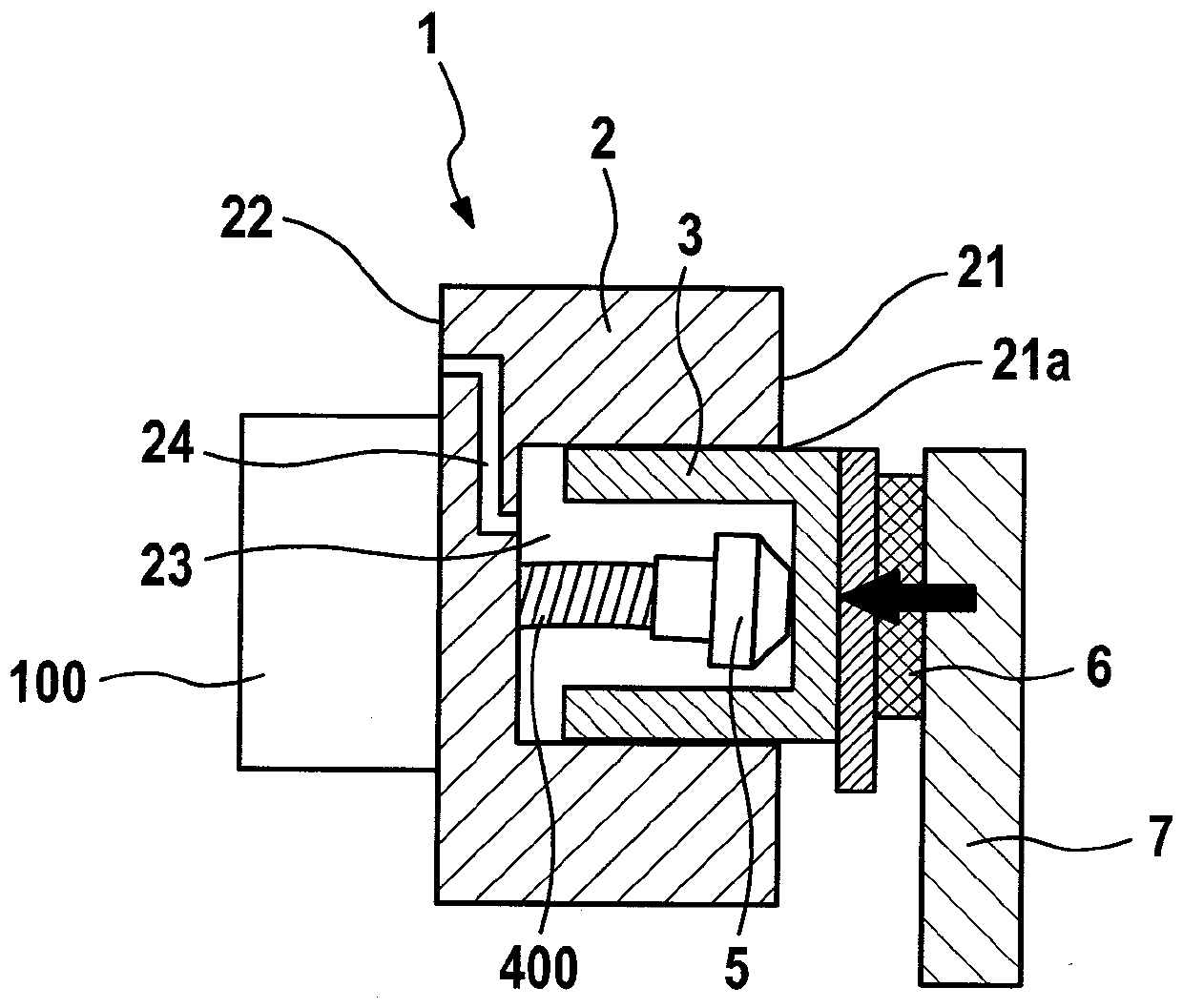
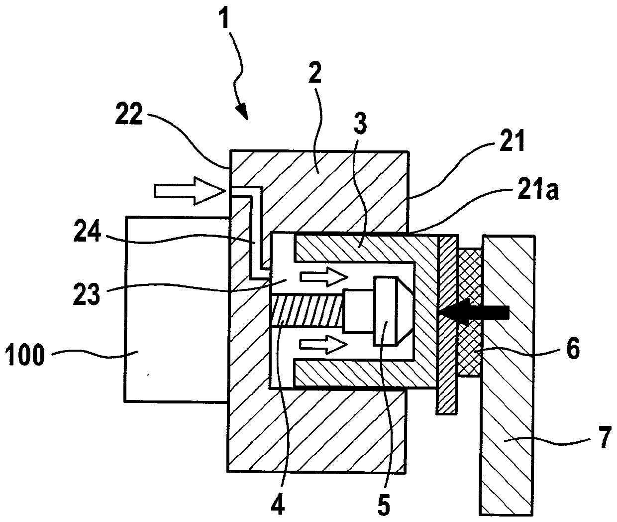
[0021] Refer below figure 2 The first embodiment of the present invention will be described. A braking device 1 for an automatic (automatic) parking brake (parking brake) comprises a brake caliper housing 2 or a brake caliper, a brake piston 3, a spindle 4, in particular a spindle, and A spindle nut 5 . Furthermore, the parking brake has an electric motor-gear unit (MGU) 100 and on the brake piston side at least one brake lining 6 and a brake disc 7 .

[0022] The caliper housing 2 comprises a first end 21 with a first opening 21 a for receiving the brake piston 3 , a second end oriented in the direction of the motor-transmission unit 100 . 22 and an inner chamber 23 for receiving fluid or brake fluid. Furthermore, hydraulic lines 24 for supplying brake fluid into the inner chamber 21 or for draining the brake fluid from the inner chamber 21 are provided in the caliper housing 2 .

[0023] The brake piston 3 is substantially cylindrical and has a blind hole pointing in th...


PUM


Abstract

A method for actuating a parking brake with a brake device (1) having a brake caliper housing (2) with an inner chamber (23) for receiving a fluid, a brake piston ( 3), a main shaft (4) and a main shaft nut (5), the method has the following steps: during the mechanical tightening of the parking brake, the hydraulic first actuation in the inner chamber (23) is detected staff pre-stress. The object of the present invention is to provide a method for releasing a braking device for an automatic parking brake and a corresponding device or a control unit, by means of which the parking brake can be released reliably and in a component-friendly manner. brakes. For this purpose, the method has the additional steps of: comparing the first driver's preload with the aid of the control unit to a predetermined pressure threshold value; creating a hydraulic support in the inner chamber (23) to relieve the load on the main shaft (4) pressure, as long as the first driver prepressure is above the pressure threshold.

Description

technical field [0001] The invention relates to a method for actuating an automatic parking brake and to a corresponding automatic parking brake and a control unit. Background technique [0002] DE 10 2004 046 871 A1 discloses a method for releasing the parking brake, in which in principle hydraulic fluid is fed into the hydraulic chamber in a first step. The electric motor is then energized such that it attempts to move the spindle nut of the braking device off the brake disc. However, the electric motor initially did not succeed in moving the main shaft because of the relatively high spring force acting on the main shaft via the spring element and the corresponding auxiliary piston. Only when the pressure in the hydraulic chamber is greater than the spring force of the spring element, which acts via the auxiliary piston, is the main shaft relieved and begins to rotate. In order to prevent the spindle from sticking, a ball is provided on the top end of the spindle to keep...

Claims


Application Information

Patent Timeline
Patent Type & Authority Patents(China)
IPC IPC(8): B60T13/74B60T13/66
CPCB60T8/17B60T8/172F16D65/18F16D2121/24F16D2121/26F16D2125/40B60T13/588B60T13/741F16D2121/02
Inventor S.豪贝尔H.沃尔夫
Owner ROBERT BOSCH GMBH
Why Eureka
Try Eureka