Liquid phase pulse discharge plasma hydrogen production device and hydrogen production method

A technology of pulse discharge and hydrogen production device, applied in chemical instruments and methods, hydrogen, inorganic chemistry, etc., can solve the problems of weakening discharge intensity, restricting the development of plasma hydrogen production, general hydrogen selectivity, etc., and achieving increased spatial distribution and density, avoid enrichment on the electrode surface, and improve the effect of hydrogen production

Active Publication Date: 2015-08-12
DALIAN MARITIME UNIVERSITY
4 Cites 3 Cited by

AI-Extracted Technical Summary

Problems solved by technology

Plasma is regarded as the fourth state besides solid, liquid, and gas. Because it contains high-energy active particles, it is widely used in the fields of environmental protection and material synthesis. However, the current method of hydrogen production using plasma is mainly in the gas phase discharge. In terms of hydrogen production technology, the disadvantages of this hydrogen production method a...

Method used

The first electrode 3 of the present invention is detachably connected with the base 2 or the liquid phase reaction chamber 1; the second electrode 4 is detachably connected with the liquid phase reaction chamber 1; the present invention utilizes high voltage pulse Liquid phase discharge technology, the high-energy electrons in the generated plasma collide with alcohol molecules to break C-H, C-O, H-O, and form a variety of new substances including hydrogen after reforming; metal electrodes are used to discharge in the liquid phase , the metal electrode plays a role similar to catalysis to decompose the alcohol solution, and the electrodes of different metal materials play different roles in the decomposition of alcohol molecules and the hydrogen production path. The plate electrode of the present invention is made of metal materials, which can be used for Stainless steel, iron, copper, etc., preferably zinc and aluminum; plate electrodes made of different metal materials have different effects on the decomposition of alcohol molecules and hydrogen production paths, and plate electrodes made of zinc or aluminum can enhance the hydrogen free radicals, hydroxyl The strength of free radicals is more conducive to the synthesis of hydrogen. The plate electrode of the present invention adopts different metal materials, and there are certain differences in the hydrogen production effect and the hydrogen production amount. The hydrogen production amount of the plate electrode using iron and copper is higher than that of the plate electrode using stainless steel materials, and the plate electrode adopts zinc, The hydrogen production effect of aluminum is better than that of iron and copper for plate electrodes. The setting of the insulating sleeve sleeved on the rod electrode is used to gather energy and prevent energy diffusion. The invention has the advantages of simple design, low cost and convenient disassembly, and is appli...

Abstract

The invention discloses a liquid phase pulse discharge plasma hydrogen production device and a hydrogen production method thereof. The hydrogen production device comprises a liquid phase reaction chamber, a base, a first electrode, a second electrode and a gas vent, wherein the base is capped on the liquid phase reaction chamber; a closed space for containing reactants and finishing a hydrogen production reaction is formed between the base and the liquid phase reaction chamber; the first electrode and the second electrode are arranged in the closed space and are opposite to each other; the first electrode and the second electrode are made of metal materials; and the gas vent is communicated with the closed space. The space distribution and density of plasma can be effectively improved, and production of hydrogen is promoted.

Application Domain

Technology Topic

Image

  • Liquid phase pulse discharge plasma hydrogen production device and hydrogen production method
  • Liquid phase pulse discharge plasma hydrogen production device and hydrogen production method
  • Liquid phase pulse discharge plasma hydrogen production device and hydrogen production method

Examples

  • Experimental program(1)

Example Embodiment

[0031] In order to make the objectives, technical solutions, and advantages of the embodiments of the present invention clearer, the technical solutions in the embodiments of the present invention will be described clearly and completely in conjunction with the accompanying drawings in the embodiments of the present invention. Obviously, the described embodiments It is a part of the embodiments of the present invention, not all the embodiments. Based on the embodiments of the present invention, all other embodiments obtained by those of ordinary skill in the art without creative work shall fall within the protection scope of the present invention.
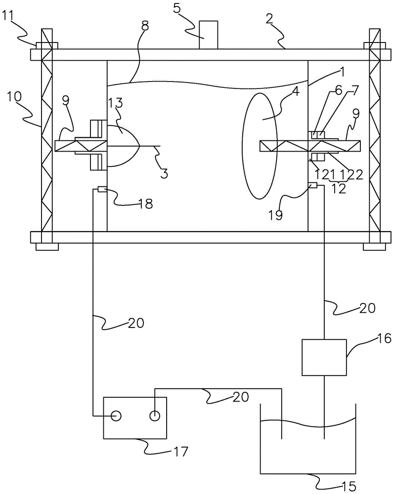
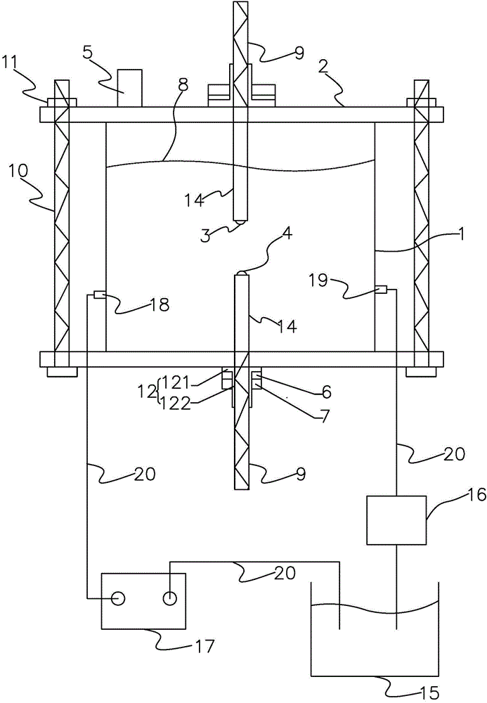
[0032] figure 1 , figure 2 It is a schematic diagram of the structure of the hydrogen production device of embodiment 1 of the present invention, in which, figure 1 The hydrogen production device shown is the case where the needle electrode and the plate electrode are arranged opposite to each other. figure 2 The hydrogen production device shown is a situation where the needle electrode and the plate electrode are arranged opposite to each other, such as figure 1 with figure 2 As shown, the hydrogen production device includes: a liquid phase reaction chamber 1; a pedestal 2 covered on the liquid phase reaction chamber 1; the pedestal 2 and the liquid phase reaction chamber 1 form a accommodating reactant and complete A closed space for the hydrogen production reaction; a first electrode 3 and a second electrode 4 placed in the closed space and opposed to each other; the first electrode 3 and the second electrode 4 are made of metal materials; and The air-conducting hole 5 connected to the enclosed space; further, the first electrode 3 and the second electrode 4 are arranged opposite to each other up and down; the first electrode 3 is connected to the base 2; the second electrode 4 is connected At the bottom of the liquid phase reaction chamber 1; further, the first electrode 3 and the second electrode 4 are arranged opposite to each other; the first electrode 3 and the second electrode 4 are respectively connected to the liquid phase reaction chamber 1 Side; further, the first electrode 3 is a needle electrode, the second electrode 4 is a plate electrode; the needle electrode is connected to the positive electrode of the high-voltage pulse power supply; the plate electrode is connected to the negative electrode of the high-voltage pulse power supply; in addition, the system The hydrogen device also includes an alcohol solution 8 contained in the liquid phase reaction chamber 1; further, the needle electrode is made of high melting point metal material; the plate electrode is made of zinc material or aluminum material; further, The liquid phase reaction chamber 1 also has a liquid inlet 18 and a liquid outlet 19; the hydrogen production device also includes an alcohol solution supply tank 15 for containing an alcohol solution supply liquid; the alcohol solution supply tank 15 passes through a pipe The path 20 connects the liquid inlet 18 and the liquid outlet 19; the hydrogen production device also includes a peristaltic pump 17 installed on the pipeline 20 between the liquid inlet 18 and the alcohol solution supply tank 15, and an installation The carbon filter 16 on the pipeline 20 between the liquid outlet 19 and the alcohol solution supply tank 15; the alcohol solution supply liquid flows out of the alcohol solution supply tank 15 and enters the liquid phase reaction through the liquid inlet 18 through the peristaltic pump 17 Chamber 1; the alcohol solution 8 in the liquid phase reaction chamber 1 flows out from the liquid outlet 19, passes through the carbon filter 16 to filter the carbon in the alcohol solution 8, and then returns to the alcohol solution supply tank 15. Further, the plate electrode is connected to the bottom of the liquid phase reaction chamber 1 or one side of the liquid phase reaction chamber 1 through a threaded rod 9, and the threaded rod 9 drawn out of the liquid phase reaction chamber 1 passes through a seal which is sequentially sleeved on it. The seat 12, the gasket 6 and the nut 7 realize sealing; the sealing seat 12 includes a first cylinder 121 and a second cylinder 122, and the inner diameters of the first cylinder 121 and the second cylinder 122 are the same as those of the threaded rod. 9 the outer diameter is adapted, the outer diameter of the second cylinder 122 is adapted to the gasket 6 and the nut 7, the outer diameter of the first cylinder 121 is greater than the outer diameter of the second cylinder 122; the needle The electrode is connected to the base 2 or the other side of the liquid phase reaction chamber 1 via a fixing seat 13; the outer surface of the fixing seat 13 is covered with a heat shrinkable tube and coated with silica gel for strengthening fixation; the alcohol solution 8 is methanol Solution or ethanol solution, and the volume fraction of alcohol used ranges from 5% to 95%; the distance between the needle electrode and the plate electrode is 1 to 30 mm; preferably, the air guide hole 5 is provided on the base 2 It can also be arranged on the liquid phase reaction chamber 1; preferably, the needle electrode is directly facing the center of the plate electrode; both ends of the base 2 and the bottom of the liquid phase reaction chamber 1 pass through the screw 10 and The fastener 11 is connected; the two screws 10 respectively pass through one end of the base 2 and the bottom of the liquid phase reaction chamber 1, and are fixed by the fastener 11; before the hydrogen production reaction, the needle electrode is first connected to Connect the plate electrode to the bottom of the liquid phase reaction chamber 1 or the other side of the liquid phase reaction chamber 1 on the side of the susceptor 2 or liquid phase reaction chamber 1, and then adjust the distance between the needle electrode and the plate electrode and pass the screw 10 The two ends of the base 2 and the bottom of the liquid phase reaction chamber 1 are connected with the fastener 11, so that the base 2 and the liquid phase reaction chamber 1 form a closed space for containing reactants and completing the hydrogen production reaction; , The distance between the needle electrode and the plate electrode is 10-15 mm; the volume fraction of alcohol used ranges from 45% to 60%; the liquid inlet 18 and the liquid outlet 19 can be opened on the side of the liquid phase reaction chamber 1 Wall; The liquid phase reaction chamber 1 is made of insulating materials such as plexiglass, or made of metal materials with greater hardness such as stainless steel, and is a container with an open top; the needle electrode is made of platinum or tungsten materials .
[0033] image 3 , Figure 4 It is a schematic diagram of the structure of the hydrogen production device of embodiment 2 of the present invention, in which, image 3 The hydrogen production device shown is a situation where two rod electrodes are arranged opposite to each other. Figure 4 The hydrogen production device shown is a situation where two rod electrodes are arranged opposite to each other, such as image 3 with Figure 4 As shown, the hydrogen production device includes: a liquid phase reaction chamber 1; a pedestal 2 covered on the liquid phase reaction chamber 1; the pedestal 2 and the liquid phase reaction chamber 1 form a accommodating reactant and complete A closed space for the hydrogen production reaction; a first electrode 3 and a second electrode 4 placed in the closed space and opposed to each other; the first electrode 3 and the second electrode 4 are made of metal materials; and The air-conducting hole 5 connected to the enclosed space; further, the first electrode 3 and the second electrode 4 are arranged opposite to each other up and down; the first electrode 3 is connected to the base 2; the second electrode 4 is connected At the bottom of the liquid phase reaction chamber 1; further, the first electrode 3 and the second electrode 4 are arranged opposite to each other; the first electrode 3 and the second electrode 4 are respectively connected to the liquid phase reaction chamber 1 Side; Further, the first electrode 3 and the second electrode 4 are rod electrodes; the rod electrode is partially sleeved in the insulating sleeve 14 so that the front end of the rod electrode is exposed outside the insulating sleeve 14 One of the rod electrodes is connected to the positive electrode of the high-voltage pulse power supply, and the other rod electrode is connected to the negative electrode of the high-voltage pulse power supply; in addition, the hydrogen production device also includes an alcohol solution 8 contained in the liquid phase reaction chamber 1; further, the The rod electrode is made of stainless steel; the insulating sleeve 14 is made of polytetrafluoroethylene; further, the liquid phase reaction chamber 1 also has a liquid inlet 18 and a liquid outlet 19; the hydrogen production device It also includes an alcohol solution supply tank 15 for accommodating an alcohol solution supply solution; the alcohol solution supply tank 15 is connected to the liquid inlet 18 and the liquid outlet 19 through a pipeline 20; the hydrogen production device also includes installation The peristaltic pump 17 on the pipeline 20 between the liquid inlet 18 and the alcohol solution supply tank 15 and the carbon filter 16 installed on the pipeline 20 between the liquid outlet 19 and the alcohol solution supply tank 15; The solution supply solution flows out from the alcohol solution supply tank 15 and enters the liquid phase reaction chamber 1 through the liquid inlet 18 through the peristaltic pump 17; the alcohol solution 8 in the liquid reaction chamber 1 flows out of the liquid outlet 19 and passes through the carbon filter 16 The carbon in the alcohol solution 8 is filtered, and then returned to the alcohol solution supply tank 15. Further, one of the rod electrodes (first electrode 3) is connected to the base 2 or the liquid phase reaction chamber 1 side through a threaded rod 9, and a threaded rod 9 is drawn from the base 2 or the liquid phase reaction chamber 1 side. The sealing is achieved by the sealing seat 12, the gasket 6 and the nut 7 which are sequentially sleeved on it; the other rod electrode (the second electrode 4) is connected to the bottom of the liquid phase reaction chamber 1 through the threaded rod 9 or the liquid phase reaction On the other side of the chamber 1, the threaded rod 9 drawn from the liquid phase reaction chamber 1 is sealed by a sealing seat 12, a gasket 6 and a screw cap 7 sequentially sleeved thereon; the sealing seat 12 includes a first cylinder 121 And the second cylinder 122, the inner diameters of the first cylinder 121 and the second cylinder 122 are matched with the outer diameter of the threaded rod 9, and the outer diameter of the second cylinder 122 is compatible with the gasket 6 and the nut 7 is suitable, the outer diameter of the first cylinder 121 is larger than the outer diameter of the second cylinder 122; preferably, the air guide hole 5 is provided on the base 2; the alcohol solution 8 is methanol solution or ethanol Solution, and the volume fraction of alcohol used ranges from 5% to 95%; the distance between the two rod electrodes is 1 to 30 mm, and is coaxial; both ends of the base 2 and the bottom of the liquid phase reaction chamber 1 It is connected by a screw 10 and a fastener 11; there are two screws 10, which respectively pass through one end of the base 2 and the bottom of the liquid phase reaction chamber 1, and are fixed by a fastener 11; before the hydrogen production reaction, first One rod electrode is connected to the base 2 or one side of the liquid phase reaction chamber 1, and the other rod electrode is connected to the bottom of the liquid phase reaction chamber 1 or the other side of the liquid phase reaction chamber 1, and then adjust the gap between the two rod electrodes. The two ends of the base 2 and the bottom of the liquid phase reaction chamber 1 are connected by the aforementioned screw 10 and the fastener 11, so that the base 2 and the liquid phase reaction chamber 1 form a accommodating reactant and complete hydrogen production A closed space for the reaction; further preferably, the distance between the two rod electrodes is 10-15mm; the volume fraction of the alcohol used ranges from 45% to 60%; the liquid inlet 18 and the liquid outlet 19 can be opened in the liquid phase The side wall of the reaction chamber 1; the liquid phase reaction chamber 1 is made of insulating materials such as organic glass, or made of metal materials with greater hardness such as stainless steel.
[0034] Such as Figure 5 As shown, a hydrogen production method of a liquid phase pulse discharge plasma hydrogen production device as described in any one of the above includes the following steps:
[0035] Step 1: Prepare an alcohol solution 8 with a volume fraction of 5%-95% and place it in the liquid phase reaction chamber 1. The liquid surface of the alcohol solution 8 submerges the first electrode 3 and the second electrode 4 and passes through the first electrode 3. And the second electrode 4 apply high voltage pulse electricity to the alcohol solution 8;
[0036] Step 2: The mixed gas containing hydrogen generated during the discharge process is discharged from the air guide hole 5 and collected and stored; the discharge form is adjusted by changing the voltage and frequency of the high-voltage pulse electricity, the discharge form includes corona discharge, spark discharge or arc discharge .
[0037] Further, when the liquid phase reaction chamber 1 further has a liquid inlet 18 and a liquid outlet 19, the hydrogen production device further includes an alcohol solution replenishment tank 15 for containing an alcohol solution replenishment liquid, which is installed at the liquid inlet 18 and the peristaltic pump 17 on the pipeline 20 between the alcohol solution supply tank 15 and the carbon filter 16 installed on the pipeline 20 between the liquid outlet 19 and the alcohol solution supply tank 15, when the hydrogen production The method also includes the following steps: the alcohol solution replenishment liquid flows out from the alcohol solution replenishment tank 15 and enters the liquid phase reaction chamber 1 through the liquid inlet 18 through the peristaltic pump 17; the alcohol solution 8 in the liquid phase reaction chamber 1 passes through the liquid outlet 19 It flows out, filters the carbon in the alcohol solution 8 through the carbon filter 16, and then returns to the alcohol solution supply tank 15.
[0038] The first electrode 3 of the present invention is detachably connected to the base 2 or the liquid phase reaction chamber 1; the second electrode 4 is detachably connected to the liquid phase reaction chamber 1; the present invention uses high-voltage pulsed liquid phase discharge Technology, the high-energy electrons in the generated plasma collide with alcohol molecules to break CH, CO, and HO, and form a variety of new substances including hydrogen after reforming; using metal electrodes to discharge in the liquid phase, metal materials The electrode has a similar catalytic effect to decompose the alcohol solution. Electrodes of different metal materials have different effects on the decomposition of alcohol molecules and the path of hydrogen production. The plate electrode of the present invention is made of metal materials, which can be stainless steel or iron. , Copper, etc., preferably zinc, aluminum; plate electrodes of different metal materials have different effects on the decomposition of alcohol molecules and the path of hydrogen production. The use of plate electrodes made of zinc or aluminum can enhance the hydrogen free radicals and hydroxyl free radicals. Strength, more conducive to the synthesis of hydrogen. The plate electrode of the present invention uses different metal materials, and there are certain differences in the hydrogen production effect and the hydrogen production volume. The hydrogen production volume of the plate electrode using iron and copper is higher than that of the plate electrode using stainless steel. The plate electrode uses zinc, The hydrogen production effect of aluminum is better than the hydrogen production effect of plate electrodes using iron and copper. The provision of an insulating sleeve sleeved on the rod electrode is used to gather energy and prevent energy diffusion. The invention has simple design, low cost and easy disassembly, and is applied to the related fields of liquid phase pulse discharge hydrogen production and plasma application.
[0039] The voltage range of the high-voltage pulsed electricity of the present invention is 1kV~60kV, and the frequency range is 1Hz~6000Hz; the voltage range of the high-voltage pulsed electricity is preferably 20kV~60kV, and the frequency range is 20Hz~40Hz; the discharge type is corona discharge, Spark discharge and arc discharge; through the form of low-frequency pulse discharge, the energy consumption is effectively reduced; the first electrode and the second electrode placed in the liquid phase reaction chamber are both submerged in the alcohol solution, and then the alcohol solution is converted into the form of liquid discharge Take hydrogen; use alcohol as a raw material to produce hydrogen, which has a wide range of sources and is reproducible.
[0040] The invention adopts the liquid phase pulse discharge hydrogen production method, which effectively increases the spatial distribution and density of the plasma and promotes the generation of hydrogen compared with the gas phase hydrogen production method; at the same time, the metal material has an enhanced effect on the liquid phase discharge hydrogen production, which is beneficial to The hydrogen production and the hydrogen production effect are improved. The hydrogen production reaction of the present invention is carried out under normal temperature and pressure, which has higher hydrogen production and energy efficiency. The alcohol replenishment device, peristaltic pump and carbon filter are set up so that the alcohol solution can be continuously replenished during the hydrogen production reaction, and through the circulation of the alcohol solution and the use of the carbon filter set on the circulation pipeline, the production of The carbon is discharged in time and filtered to avoid carbon accumulation on the electrode surface.
[0041] The implementation process of the present invention will be illustrated by specific examples. The ethanol solution with a volume fraction of 45% is placed in the liquid phase reaction chamber, and the ethanol solution is acted on by a high voltage pulse with a frequency of 30 Hz and a voltage of 30 kV. The first electrode is a needle. Electrode, the second electrode is a plate electrode, the plate electrode is made of aluminum material, the discharge type is spark discharge, the hydrogen production flow rate is 3028mL/min, the hydrogen selectivity is 71.25%, and the energy consumption is about 0.28kW·h/m 3.

PUM

no PUM

Description & Claims & Application Information

We can also present the details of the Description, Claims and Application information to help users get a comprehensive understanding of the technical details of the patent, such as background art, summary of invention, brief description of drawings, description of embodiments, and other original content. On the other hand, users can also determine the specific scope of protection of the technology through the list of claims; as well as understand the changes in the life cycle of the technology with the presentation of the patent timeline. Login to view more.

Similar technology patents

Liquid phase pulse discharge hydrogen production device without carbon deposit on surfaces of electrodes and hydrogen production method thereof

InactiveCN104891437AIncrease spatial distribution and densityPromotes the production of hydrogen gasHydrogenChemistryHydrogen production
Owner:DALIAN MARITIME UNIVERSITY

Processes for increasing an octane value of a gasoline component

ActiveUS20200407649A1Promote productionReduce amountNaphtha treatmentGasoline stabilisationCyclohexanesProcess engineering
Owner:UOP LLC

Blind rivet nut

ActiveUS20180112702A1Reduce material and thus massPromote productionNutsBoltsEngineeringRivet
Owner:GESIPA BLINDNIETTECHNIK GMBH

Classification and recommendation of technical efficacy words

  • Promote production
  • Increase spatial distribution and density

Display device

ActiveUS20080203898A1Promote productionChromatic purity is improvedIncadescent screens/filtersDischarge tube luminescnet screensOptoelectronicsRed light
Owner:SEIKO EPSON CORP

Injection of bone marrow-derived conditioned medium for angiogenesis

InactiveUS20060051334A1Enhances blood vessel formationPromote productionBiocidePeptide/protein ingredientsHypoxia-inducible factorsGreek letter alpha
Owner:MEDIVAS LLC

Liquid phase pulse discharge hydrogen production device without carbon deposit on surfaces of electrodes and hydrogen production method thereof

InactiveCN104891437AIncrease spatial distribution and densityPromotes the production of hydrogen gasHydrogenChemistryHydrogen production
Owner:DALIAN MARITIME UNIVERSITY
Why Eureka
Try Eureka