Automatic dust removing method, automatic dust removing system and vehicle

An automatic dust removal and engine technology, which is applied to the cooling of engine components, machines/engines, and engines, can solve the problems of low cleaning efficiency, time-consuming and laborious, and inability to accurately grasp the timing of dust removal in the engine cooling system.

Active Publication Date: 2015-08-12
BEIQI FOTON MOTOR CO LTD
View PDF7 Cites 12 Cited by
  • Summary
  • Abstract
  • Description
  • Claims
  • Application Information

AI Technical Summary

Problems solved by technology

Since the corrugated fins of the cooling device are densely distributed, the manual cleaning method is not only time-consuming and labor-intensive, but also has extremely low cleaning efficiency and unsatisfactory results; in addition, because this cleaning method generally determines the time for dust removal by the operator based on his own experience, Therefore, it is impossible to accurately grasp the best timing of dust removal for the engine cooling system. It is often after the engine has been working at a non-preset temperature for a long period of time that the operator finds that the dust removal operation should be performed, which will inevitably cause great damage to the engine. harm

Method used


Image

  • Automatic dust removing method, automatic dust removing system and vehicle
  • Automatic dust removing method, automatic dust removing system and vehicle
  • Automatic dust removing method, automatic dust removing system and vehicle

Examples


Embodiment Construction

[0024] Exemplary embodiments of the present disclosure will be described in more detail below with reference to the accompanying drawings. Although exemplary embodiments of the present disclosure are shown in the drawings, it should be understood that the present disclosure may be embodied in various forms and should not be limited by the embodiments set forth herein. Rather, these embodiments are provided for more thorough understanding of the present disclosure and to fully convey the scope of the present disclosure to those skilled in the art.

[0025] Example of automatic dust removal method:

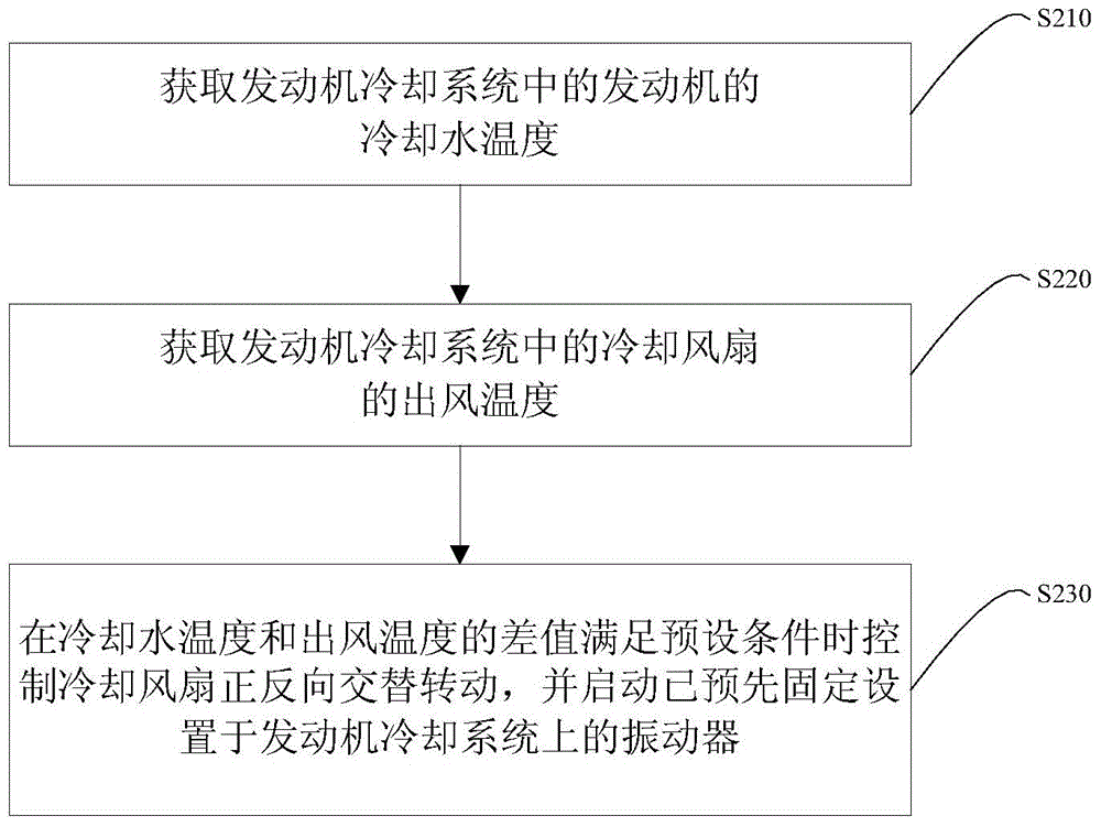
[0026] see figure 2 , figure 2 It is a schematic flow chart of the automatic dust removal method provided by the embodiment of the present invention, and the method can automatically remove dust from the engine cooling system. As shown in the figure, the method includes the following steps:

[0027] Coolant temperature obtaining step S210, obtaining the coolant temperature t1 ...


PUM


Abstract

The invention provides an automatic dust removing method, an automatic dust removing system and a vehicle. The automatic dust removing method comprises the steps of obtaining cooling liquid temperature of an engine in an engine cooling system, obtaining the air outlet temperature of a cooling fan in the engine cooling system, and when the difference value of the cooling liquid temperature and the air outlet temperature is larger than the preset temperature, controlling the cooling fan to alternatively rotate forwards and reversely. Alternative air generated by rotation in the forward and reverse direction of the cooling fan is utilized for completing automatic dust removing of the engine cooling system; the heat dissipation efficiency of the engine cooling system is improved, and meanwhile, it is also ensured that when the engine operates under the normal working temperature, the service life of the engine is prolonged.

Description

technical field [0001] The invention relates to the technical field of vehicles, in particular to an automatic dust removal method, an automatic dust removal system and a vehicle with the automatic dust removal system. Background technique [0002] As we all know, the engine will generate a lot of heat during the working process, which will increase the temperature of the engine and seriously affect the performance of the engine. In order to make the engine work within the normal temperature range, a cooling system is generally set for the engine. figure 1 It is a structural schematic diagram of a commonly used engine cooling system. As shown in the figure, the engine cooling system includes a radiator 2' and an electronic fan 3'. For some cooling systems, it may also include an intercooler (not shown in the figure), Condenser (not shown in the figure) and oil cooler (not shown in the figure). Wherein, intercooler, condenser, oil cooler and radiator 2' are connected as an ...

Claims


Application Information

Patent Timeline
Patent Type & Authority Applications(China)
IPC IPC(8): F01P11/06
CPCF01P11/06F01P2011/063
Inventor 孙韶阳李国红
Owner BEIQI FOTON MOTOR CO LTD
Why Eureka
Try Eureka