
In-situ pore water sampling column and water sampling method thereof

A collection method and pore water technology, applied in the direction of sampling devices, etc., can solve the problems of Bou-Rouch sampler equipment structural damage, Bou-Rouch sampler work failure, and inability to meet the requirements effectively, so as to improve adaptability and resistance , The operation method is simple and standardized, and the effect of improving work efficiency

Active Publication Date: 2015-08-12
CHENGDU OUXUN TECH CO LTD
View PDF5 Cites 10 Cited by
  • Summary
  • Abstract
  • Description
  • Claims
  • Application Information

AI Technical Summary

Problems solved by technology

[0002] At present, when conducting deep-sea exploration and geological research, it is often necessary to collect the in-situ pore water contained in the deep seabed sea mud. The depth of the seabed is generally not less than 4,000 meters. The bottom of the deep ocean cannot be directly collected by divers directly underwater, and it must be collected with the help of in-situ pore water sampling equipment. The Bou-Rouch sampler is currently the most widely used sampling device when the standpipe sampling method is adopted. However, when collecting a lot of pore water at the bottom of the ocean, it is very easy to cause the Bou-Rouch sampler to fail due to excessive ocean pressure, and even cause damage to the structure of the Bou-Rouch sampler in severe cases. At the same time, when the Bou-Rouch sampler is sampling, the degree of automation is relatively low, so the Bou-Rouch sampler cannot effectively meet the needs of sampling pore water in the deep sea environment below 4000 meters. , there is an urgent need to develop a professional deep-sea environment in-situ pore water sampling equipment to meet the needs of practical use

Method used


Image

  • In-situ pore water sampling column and water sampling method thereof
  • In-situ pore water sampling column and water sampling method thereof
  • In-situ pore water sampling column and water sampling method thereof

Examples


Embodiment Construction

[0018] In order to make the technical means, creative features, goals and effects achieved by the present invention easy to understand, the present invention will be further described below in conjunction with specific embodiments.

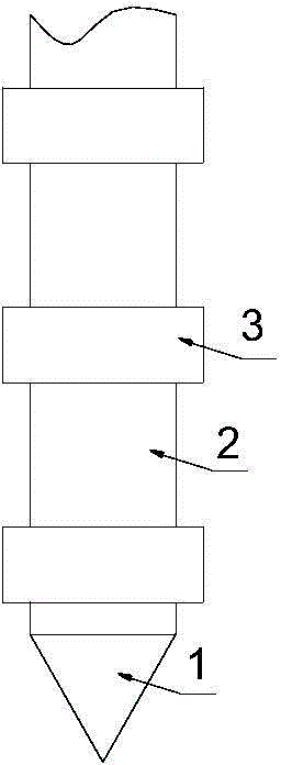
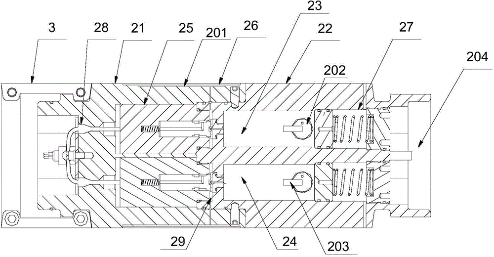
[0019] Such as figure 1 with 2 The in-situ pore water collection column includes a drilling head 1 and a water collection device unit 2, at least two water collection device units 2 are connected by clamps 3, and the water collection device units 2 are coaxially distributed. The head 1 is connected with the water collector unit 2 through the clamp 3, and is coaxially distributed with the water collector unit 2.

[0020] In the present embodiment, the described water collector unit 2 includes a solenoid valve installation bucket 21, a sampling cylinder 22, a waste water cabin 23, a sample water cabin 24, a solenoid valve 25, a composite filter layer 26, a balance piston 27, a control cable 28 and The guide tube 29, the electromagnetic valve insta...


PUM

PropertyMeasurementUnit
depthaaaaaaaaaa

Abstract

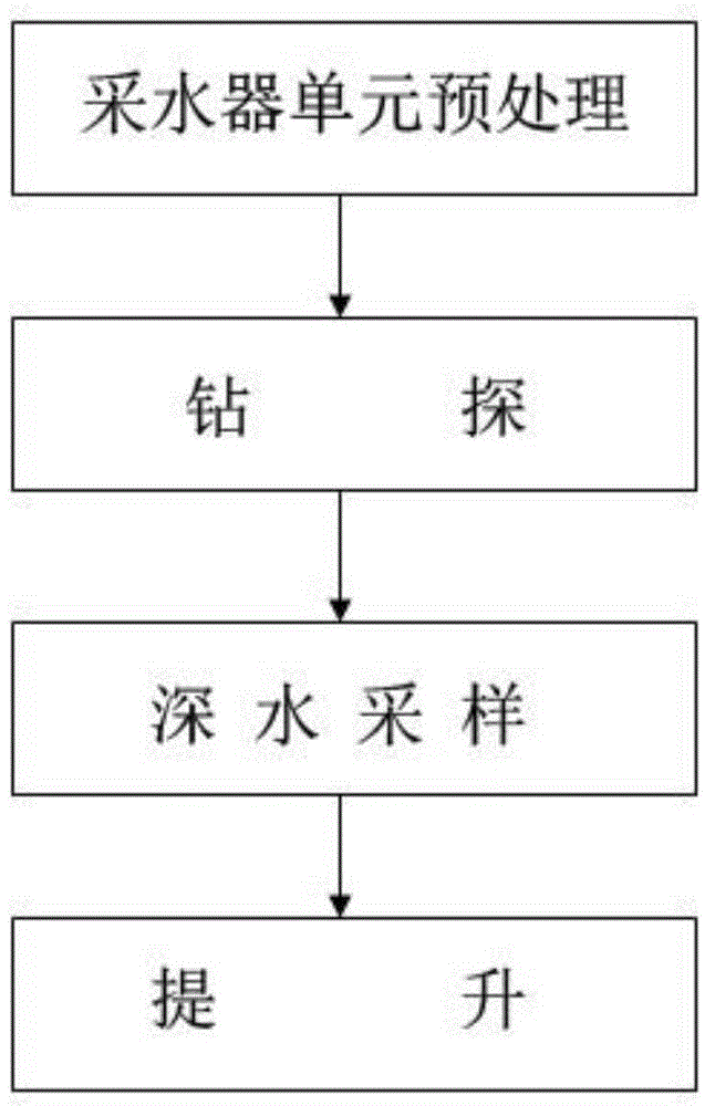
The invention relates to an in-situ pore water sampling column and a water sampling method thereof. The in-situ pore water sampling column comprises a drilling head and at least two sampler units; the sampler units are connected through a hoop; each sampler unit comprises an electromagnetic valve mounting barrel, a sampling tube, a wastewater cabin, a sample cabin, an electromagnetic valve, a composite filter layer, a balance piston, a control cable and a guide pipe. The water sampling method includes the steps of preprocessing of the sampler units, drilling, deep-water sampling and lifting. The in-situ pore water sampling column and the water sampling method thereof have the advantages that deep bed water can be effectively sampled under high purity, the ability of equipment to adapt to and resist marine pressure changes is improved, operational stability and reliability of equipment is improved, operating is simple and regular, efficiency of deep bed water sampling is effectively improved, and operational skill level of operators can be increased.

Description

technical field [0001] The invention relates to an in-situ pore water sampling water column and a water sample collection method, belonging to the technical field of marine exploration equipment. Background technique [0002] At present, when conducting deep-sea exploration and geological research, it is often necessary to collect the in-situ pore water contained in the deep seabed sea mud. The depth of the seabed is generally not less than 4,000 meters. The bottom of the deep ocean cannot be directly collected by divers directly underwater, and it must be collected with the help of in-situ pore water sampling equipment. The Bou-Rouch sampler is currently the most widely used sampling device when the standpipe sampling method is adopted. However, when collecting a lot of pore water at the bottom of the ocean, it is very easy to cause the Bou-Rouch sampler to fail due to excessive ocean pressure, and even cause damage to the structure of the Bou-Rouch sampler in severe cases...

Claims


Application Information

Patent Timeline
Patent Type & Authority Applications(China)
IPC IPC(8): G01N1/14
Inventor 俞祖英徐著华王洪杰荣一辚李康健乐祥茂杜维纬李慧
Owner CHENGDU OUXUN TECH CO LTD
Learn More