
Electro-optical intensity modulator automatic bias control device and automatic bias control method

An electro-optical intensity modulation and electro-optical modulator technology, which is applied in the direction of logic circuits using optoelectronic devices, logic circuits using specific components, etc., can solve the problem of impure spectral components of the output signal, cannot effectively overcome the malfunction of the control loop, and takes a long time. and other problems, to achieve long-term stable and reliable tracking, and overcome the problem of control loop misoperation.

Active Publication Date: 2018-08-14
THE 41ST INST OF CHINA ELECTRONICS TECH GRP
View PDF5 Cites 0 Cited by
  • Summary
  • Abstract
  • Description
  • Claims
  • Application Information

AI Technical Summary

Problems solved by technology

[0013] In the low-frequency perturbation mode, due to the low-frequency components mixed into the modulated signal, the spectral components of the output signal will be impure. At the same time, since the modulator itself is modulated by multiple frequencies, there will be nonlinear effects, and the more modulated signal spectrum, The stronger the nonlinear effect, the stronger the output high-frequency harmonic components. Although it stabilizes the linear operating point, it also introduces other spectral components
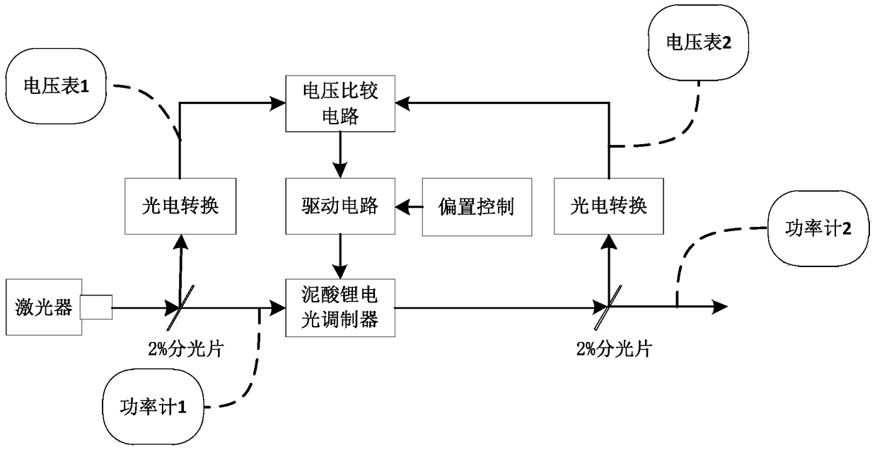
[0014] The feedback control method under the existing average power mode is greatly improved compared with the previous method, but the current method requires manual adjustment and positioning of the working point by manual participation, and at the same time, the half-wave voltage of the electro-optic modulator needs to be adjusted. Determination, this method requires more auxiliary instruments to complete the realization of the entire control, this method takes a long time and is cumbersome to operate
[0015] None of the current methods can effectively overcome the malfunction of the control loop caused by laser output jitter, because when the output power of the laser jitters briefly, it does not affect the linear operating point of the electro-optic modulator, and the current device often causes malfunction. Action, make the system in a transient nonlinear region, and output a distorted modulation signal

Method used


Image

  • Electro-optical intensity modulator automatic bias control device and automatic bias control method
  • Electro-optical intensity modulator automatic bias control device and automatic bias control method
  • Electro-optical intensity modulator automatic bias control device and automatic bias control method

Examples


Embodiment Construction

[0053] combined with Figures 2 to 5 The specific embodiment of the present invention is described further:

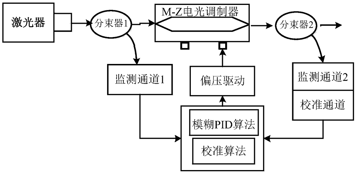
[0054] An electro-optical intensity modulator automatic bias control device, such as figure 2 As shown, the electro-optic intensity modulator is an M-Z type electro-optic intensity modulator, including a laser, a beam splitter, and an M-Z type electro-optic intensity modulator, and the beam splitter includes a first beam splitter and a second beam splitter. The first beam splitter is connected between the light exit port of the laser and the light entry port of the M-Z type electro-optic intensity modulator, and the first beam splitter is connected with an input feedback path of the electro-optic modulator. The second beam splitter is connected to the light output port of the M-Z type electro-optic intensity modulator, and the second beam splitter is connected to an output feedback path of the electro-optic modulator. The input feedback path of the electro-optic mod...


PUM


Abstract

The invention discloses an automatic bias control device for an electro-optical intensity modulator and an automatic bias control method thereof. The electro-optical intensity modulator automatic bias control device includes a laser, a beam splitter, and an M-Z type electro-optical intensity modulator. The input feedback path of the electro-optic modulator and the output feedback path of the electro-optic modulator are combined through the feedback processor to form a dual-track tracking feedback control system. The invention adopts a digital PID algorithm, adjusted by a bias driving circuit, realizes automatic and accurate positioning and tracking of the linear working point of the electro-optic modulator, and can also overcome the problem of controller malfunction caused by the jitter of the output power of the laser.

Description

technical field [0001] The invention relates to the field of electro-optic intensity modulation, in particular to an automatic bias control device and an automatic bias control method for an M-Z type electro-optical intensity modulator. Background technique [0002] The commonly used Mach-Zehnder structure electro-optic modulator uses the linear electro-optic effect to adjust the refractive index of the material, and uses M-Z interference to make the output optical power change with the applied voltage. However, since the modulation characteristics of the electro-optic modulator will change with changes in the ambient temperature and other reasons, the static operating point deviates from the midpoint of the linear region of the modulation characteristic curve, resulting in distortion of the modulated light wave signal. In the application of CATV and ROF systems, the control method of adding micro-disturbance is often used, but in this method, low-frequency signals will be m...

Claims


Application Information

Patent Timeline
Patent Type & Authority Patents(China)
IPC IPC(8): H03K19/14
Inventor 张爱国魏石磊李宝瑞汪磊
Owner THE 41ST INST OF CHINA ELECTRONICS TECH GRP
Learn More