Piercing introducer with tear-off sheath

An introducer and tear-off sheath technology, which is applied in the field of puncture introducer, can solve the problems of smooth removal of an outer sheath, restricting the use of a drainage tube, etc., and achieves the effects of simple structure, low cost, and alleviation of pain and suffering

Active Publication Date: 2017-10-13
ANHUI AOFO MEDICAL EQUIP TECH
View PDF5 Cites 3 Cited by
  • Summary
  • Abstract
  • Description
  • Claims
  • Application Information

AI Technical Summary

Problems solved by technology

In modern medical devices, the rear end of most drainage tubes has an enlarged joint for externally connecting other medical equipment for monitoring and testing. Therefore, when using the aforementioned puncture guide needle, although the drainage tube can be guided through the The needle is implanted in the chest cavity, bladder, abdominal cavity and other organs, but due to the enlarged joint at the back end of the drainage tube, the external sheath cannot be removed smoothly, which limits the use of this type of drainage tube and brings certain troubles to medical staff

Method used


Image

  • Piercing introducer with tear-off sheath
  • Piercing introducer with tear-off sheath
  • Piercing introducer with tear-off sheath

Examples


Embodiment 1

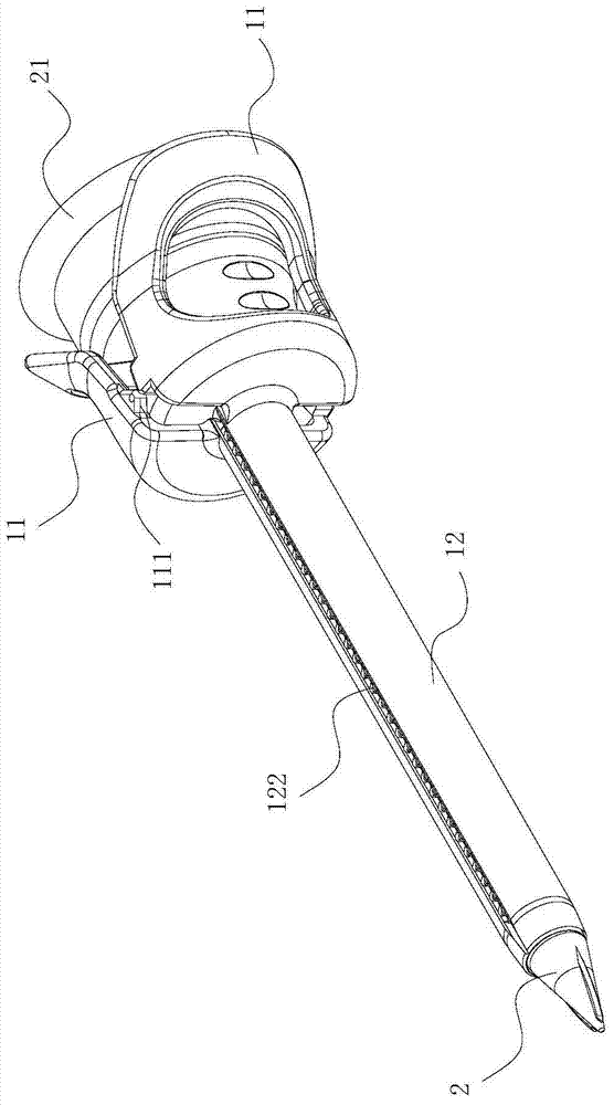
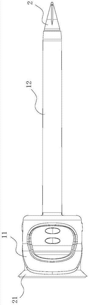
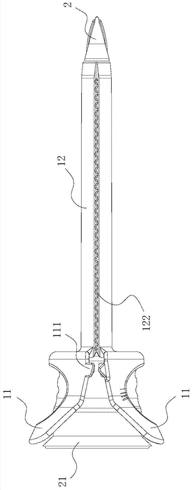
[0026] see Figure 1 to Figure 5 , the puncture introducer with a tear-off sheath includes a sheath 1 and a needle core 2 nested in the sheath 1, and the whole is rod-shaped. The two ends of the sheath 1 are open, the rear end is enlarged, and it is composed of two trumpet-shaped sheaths 11. On both symmetrical sides of the rod body 12, grooves 121 are arranged along the length direction. The grooves 121 are provided with tearing openings. In this embodiment, the tear opening is a continuous threaded opening 122 . The direction of the gap between the two sheath bodies 11 is consistent with the direction of the groove 121 on the rod body 12 . A pair of buckles 111 that match each other are arranged at the symmetrical position of the sheath body 11 where the two petal sheath bodies 11 are close to the rod body 12. The buckle 111 is divided into a male buckle and a female buckle. If it protrudes outward, the shape of the female buckle is concave inward, so that it is not easy t...

Embodiment 2

[0031] see Figure 8 to Figure 9 , the puncture introducer with a tear-off sheath includes a sheath 1 and a needle core 2 nested in the sheath 1, and the whole is rod-shaped. The two ends of the sheath 1 are open, the rear end is enlarged, and it is composed of two trumpet-shaped sheaths 11. On both symmetrical sides of the rod body 12, grooves 121 are arranged along the length direction. The grooves 121 are provided with tearing openings. In this embodiment, the tear opening is a plurality of small holes 123, and the diameter of the small holes 123 at the front end of the rod body 12 is larger than the diameter of the small holes 123 at the rear end of the rod body 12, so the distribution of the small holes 123 at the rear end of the rod body 12 is large. dense, the small holes 123 located at the front end of the rod body 12 are loosely distributed. The direction of the gap between the two sheath bodies 11 is consistent with the direction of the groove 121 on the rod body 12...


PUM


Abstract

Disclosed in the invention is a puncture guiding device capable of tearing and removing a sheath. The puncture guiding device comprises a casing sheath and a pin embedded into the casing sheath; and the casing sheath and the pin are in integrated modes. The guiding device is characterized in that the two ends of the casing sheath are open; the rear end of the sheath is expanded and is formed by two horn-shaped sheath bodies; grooves are formed in two symmetric sides of a rod body along the length direction; and tearing openings are formed in the grooves. A pair of mutually-matched buckles is arranged at symmetric positions, where the rod body approaches the positions and the two sheath bodies approach each other mutually, of the sheath bodies. The pointed end of the pin is in a shape of a solid cone; and the rear end of the pin is an expanding body matching the sheath bodies of the casing sheath. According to the invention, the structure is simple and the cost is low. Because of the change of the casing sheath structure, the puncture guiding device is suitable for various drainage tubes, especially ones with rear parts with expanding connectors; and the casing sheath can be removed from the wound of a patient in a tearing mode and the implementation is easy to carry out, so that little trauma is caused and thus the pain of the patient suffering from sickness can be substantially reduced.

Description

technical field [0001] The invention relates to the field of medical instruments, in particular to a puncture introducer with a tearable sheath. Background technique [0002] In modern medical treatment, most of the drainage operations are to make small incisions in the chest, bladder, abdominal cavity and other organs through surgery, and then implant the drainage tube through the incision site. This method is not only complicated, but also brings great trauma to the patient. And a certain amount of pain, and to observe the changes in the condition of the patient's incision site in real time, so as to avoid new problems such as cross-infection. Therefore, a new medical method has emerged to achieve drainage—the puncture guide needle, which includes a sheath and a needle core nested in the sheath. After the puncture is completed through the needle core, the internal needle core is taken out. The outer sheath is left, and then the drainage tube is inserted into the sheath to...

Claims


Application Information

Patent Timeline
Patent Type & Authority Patents(China)
IPC IPC(8): A61M25/06
Inventor 周化庆周本原
Owner ANHUI AOFO MEDICAL EQUIP TECH
Why Eureka
Try Eureka