Hot rolled strip steel rolling force optimal-setting method

A technology for optimizing setting and rolling force, applied in metal rolling, metal rolling, manufacturing tools, etc.

Active Publication Date: 2015-08-19
张家港市欧美轻工工具制造有限公司
View PDF11 Cites 16 Cited by
  • Summary
  • Abstract
  • Description
  • Claims
  • Application Information

AI Technical Summary

Problems solved by technology
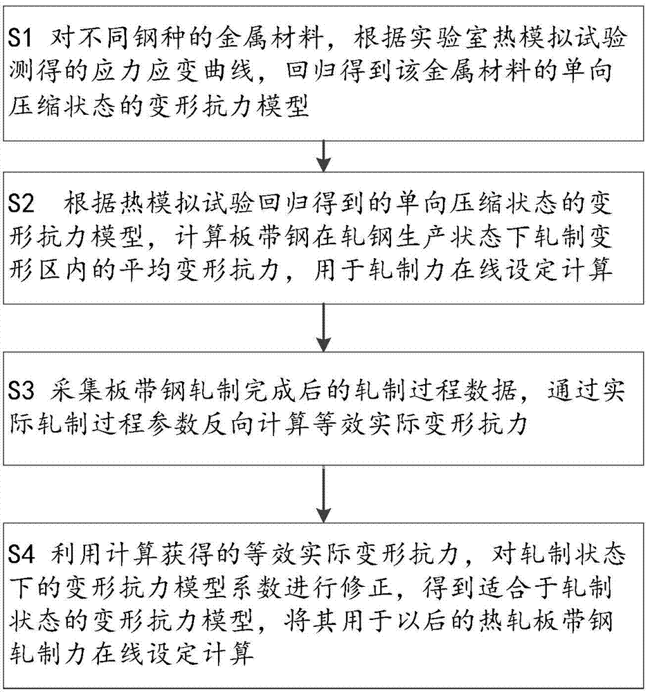
[0005] The purpose of the present invention is to solve the problems existing in the prior art, and propose a method for optimizing the rolling force of hot-rolled strip steel, which is obtained by regression of the actual performance data of stee

Method used


Image

  • Hot rolled strip steel rolling force optimal-setting method
  • Hot rolled strip steel rolling force optimal-setting method
  • Hot rolled strip steel rolling force optimal-setting method

Examples


Embodiment 1

[0112] A thermal simulation test is performed on a metal sample of a certain steel type, and the temperature function g(T)=T is taken. The deformation resistance model of the unidirectional compression state measured by the test is shown in formula (16).

[0113]

[0114] The steel grade is produced on a certain steckel rolling mill, and the measured rolling process parameters are shown in Table 1. The relationship between rolling temperature and deformation resistance is shown in Table 2; the deformation resistance model coefficients before and after correction are shown in Table 3; the calculated rolling force and measured rolling force before and after correction are shown in Table 4. It can be seen from Table 4 that the calculated rolling force after correction is very close to the actual rolling force.

[0115] Table 1 Measured rolling process parameters

[0116]

[0117] Table 2 Relationship between temperature and deformation resistance ratio

[0118]

[0119...

Embodiment 2

[0125] Do a thermal simulation test on another steel type metal sample, take the temperature function limited m 3 = 0, the stress-strain curve measured in the test is regressed, and the deformation resistance model is obtained as shown in formula (17).

[0126]

[0127] The steel grade is produced on a hot continuous rolling mill, and the measured rolling process parameters are shown in Table 5. The relationship between rolling temperature and deformation resistance is shown in Table 6; the deformation resistance model coefficients before and after correction are shown in Table 7; the calculated rolling force and measured rolling force before and after correction are shown in Table 8. It can be seen from Table 8 that the calculated rolling force after correction is very close to the actual rolling force.

[0128] Table 5 Measured rolling process parameters

[0129]

[0130] Table 6 Relationship between temperature and deformation resistance ratio

[0131]

[0132...


PUM


Abstract

The invention provides a hot rolled strip steel rolling force optimal-setting method and relates to the technical field of control of hot rolled strip steel production process. The problem that in the prior art, a laboratory thermal simulation test and rolled steel production actual data are not simultaneously utilized to conduct optimal setting on rolling force is solved. According to the hot rolled strip steel rolling force optimal-setting method, a stress strain curve of a material is measured through a laboratory thermal simulation single-pass test and is regressed into a deformation resistance model in a one-way compression state, then a deformation resistance model coefficient in an actual rolling state is corrected according to actual rolling process parameters for future rolling force setting and calculation, accordingly the setting accuracy of a hot rolled strip steel rolling force model is improved, and overload phenomenon and the like are avoided. The hot rolled strip steel rolling force optimal-setting method is suitable for rolling force setting and calculation under the condition that the actual rolling process data of multiple-pass hot rolled strip steel are obtained when the deformation resistance model for the rolling force mode is obtained through data regression measured through a laboratory heat simulation machine.

Description

technical field [0001] The invention relates to the technical field of production process control of hot-rolled strip steel, in particular to a method for optimally setting the rolling force of hot-rolled strip steel. Background technique [0002] Rolling force is the most important force parameter in the production process of hot strip strip. Accurately predicting the rolling force of each stand in finish rolling is of great significance for improving the thickness control accuracy of the strip plate, optimizing the load distribution, and ensuring the safety of equipment, and has always been concerned by people. [0003] In the calculation of rolling force, the deformation resistance model of metal should be used, and the deformation resistance can generally be expressed as a function of chemical composition, temperature, strain and strain rate. The deformation resistance model for different steel types can be measured by the Gleeble simulation test machine in the laborato...

Claims


Application Information

Patent Timeline
IPC IPC(8): B21B37/28B21B38/08
CPCB21B37/28B21B38/08
Inventor 李维刚周巍
Owner 张家港市欧美轻工工具制造有限公司
Why Eureka
Try Eureka