Al technical title is built by PatSnap Al team. It summarizes the technical point description of the patent document.
A technology of quenching furnace and quenching tank, which is applied in the field of quenching furnace, can solve problems such as safety hazards, manual participation, fixed position pick-up, complex structure, etc., and achieve the effects of prolonging life, reducing heat loss, and uniform temperature
Active Publication Date: 2015-08-19
JIASHAN THREE STAR BEARING
View PDF9 Cites 7 Cited by
Summary
Abstract
Description
Claims
Application Information
AI Technical Summary
This helps you quickly interpret patents by identifying the three key elements:
Problems solved by technology
Method used
Benefits of technology
Problems solved by technology
The quality of the lifting mechanism will directly affect the working performance of the whole crane. The lifting mechanism is mainly composed of a driving device, a transmission device, a reel, a pulley block, a pick-up device and a braking device. In addition, various auxiliary devices can also be installed. Devices, such as lifting height limiters, moment limiters, three-turn protection and other safety devices, especially on medium and large tonnage cranes, moment limiters are becoming more and more important. However, commonly used lifting mechanisms have complex structures and are often used in The process of taking workpieces also requires manual participation and fixed position pick-ups, etc., which causes some inconvenience and also poses safety hazards to workers; the quenching tank is a container filled with quenching medium. When the workpiece is immersed in the tank to cool, it needs energy Ensure that the workpiece is quenched evenly with a reasonable cooling system, so that the workpiece meets the technical requirements. The structure of the quenching tank is relatively simple, mainly composed of tank body, medium supply or discharge pipe, overflow tank, etc., and some additional heaters, Cooler, agitator, smoke exhaust and fire prevention device, etc.; however, the temperature change of the quenching tank plays a very important role in the cooling and quenching of the workpiece. If the temperature can be changed uniformly, the cooling device can cool the workpiece evenly, and the workpiece Quenching is very important
Method used
Image
Click on the blue label to locate the original text in one second.
Reading with bidirectional positioning of images and text.
Examples
Embodiment Construction
[0027]In order to make the technical means, creative features, goals and effects achieved by the present invention easy to understand, the present invention will be further elaborated below in conjunction with illustrations and specific embodiments.
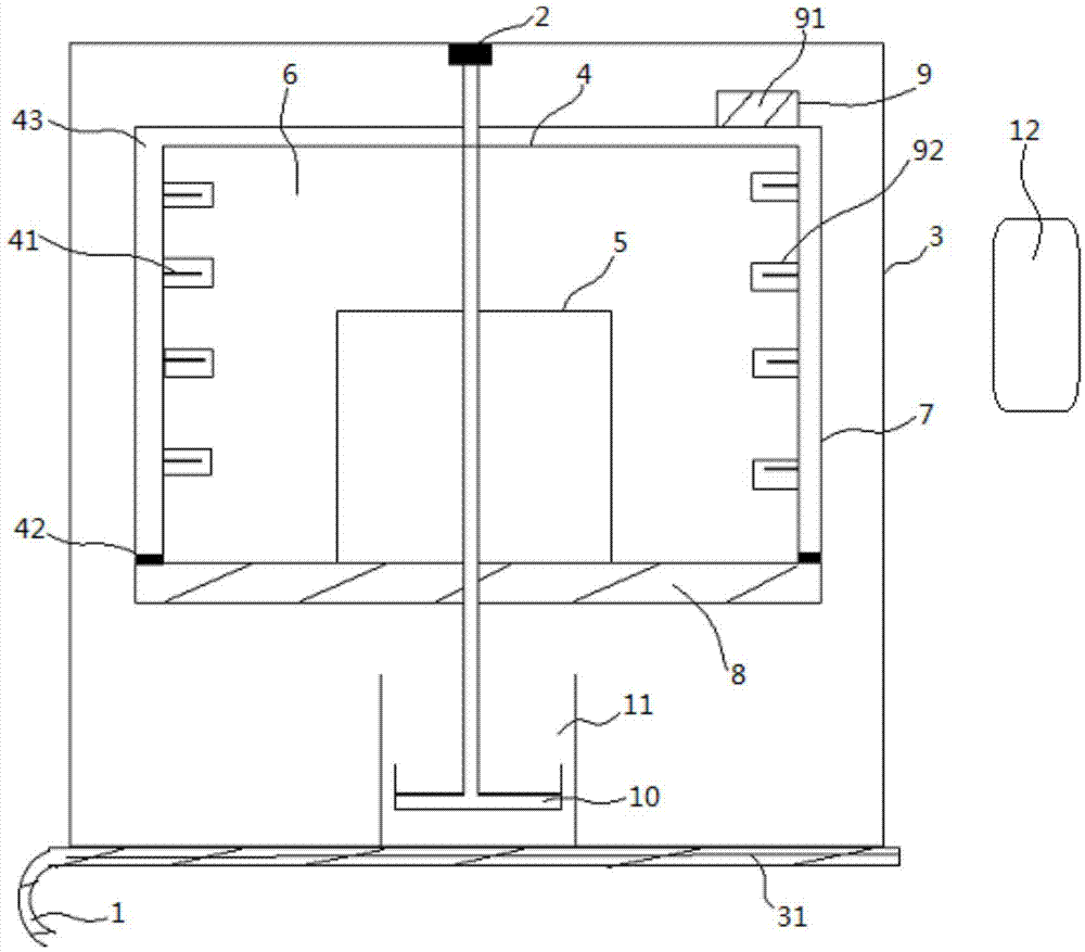
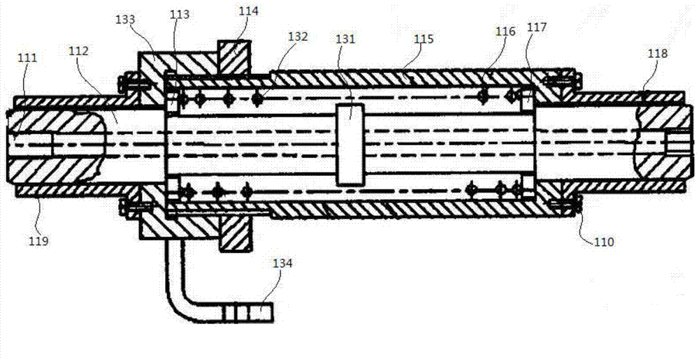
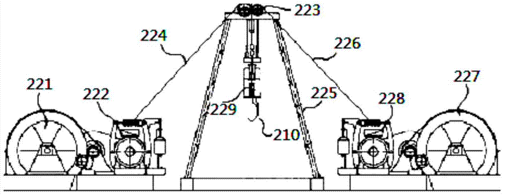
[0028] refer to figure 1 , figure 2 , image 3 and Figure 4 As shown, the quenching furnace includes a push-pull mechanism 1, a lifting mechanism 2, a bracket 3, a furnace body 4, a furnace cover 5, a furnace hearth 6, a furnace shell 7, a furnace door 8, a thermal cycle system 9, a material basket 10 and a quenching tank 11; The main body of the quenching furnace is a furnace body 4, and the main body of the furnace body 4 is a heating furnace 43. The heating furnace 43 is sequentially provided with a furnace shell 7, a furnace hearth 6 and a furnace cover 5 from the outside to the inside, and the furnace shell 7 is located at the outermost layer of the furnace body 4. A layer of rubber asbestos board is attached to the inn...
PUM
Abstract
The invention provides a quenching furnace comprising a push-pull mechanism, a lifting mechanism, a bracket, a furnace body, a furnace cover, a hearth, a furnace shell, a furnace door, a thermal cycling system, a charging basket and a quenching tank, wherein the main body of the quenching furnace is the furnace body, the main body of the furnace body is a heating furnace, the furnace shell, the hearth and the furnace cover are arranged in the heating furnace, and a heating element and the furnace cover are arranged in the hearth; the thermal cycling system is arranged at the upper end of the furnace body; a furnace opening is formed in the lower end of the furnace body, and a refractory fiber cotton sand sealing cutter is arranged at the connection part between the furnace door and the furnace body; the bracket is arranged at the two sides of the furnace body, and a control cabinet is arranged at one side of the bracket; a layer of rubber asbestos plate is attached to the inner surface of the furnace shell and can achieve an effect of heat insulation, thereby reducing the loss of heat, saving energy sources, protecting the surface of the furnace shell from being corroded, and prolonging the service life of equipment; and a self-locking device is arranged in each of a reduction box I and a reduction box II in the lifting mechanism, so that the charging basket can be stopped or slowed down at any position, the accuracy for positioning the charging basket is improved, and the charging basket is prevented from rapidly impacting the quenching tank and damaging the equipment when coming down.
Description
technical field [0001] The invention relates to the field of processing and quenching devices for castings in industry, in particular to a quenching furnace. Background technique [0002] The quenching furnace is a non-standard electric furnace specially designed according to user requirements. It is mainly used for heat treatment such as quenching and heating of various workpieces in the aluminum industry. The quenching furnace is suitable for solution heat treatment and aging treatment of large and medium-sized aluminum alloy product parts; quenching The furnace mainly includes a lifting mechanism, a push-pull mechanism, a heating furnace and a quenching tank. Only when the components cooperate effectively can the efficiency be improved; the push-pull mechanism is generally composed of a walking system, a power system, a hydraulic system, a working system, and an electrical system. The hydraulic system is a push-pull system. The main control system of the mechanism, the hy...
Claims
Application Information
Patent Timeline
Application Date:The date an application was filed.
Publication Date:The date a patent or application was officially published.
First Publication Date:The earliest publication date of a patent with the same application number.
Issue Date:Publication date of the patent grant document.
PCT Entry Date:The Entry date of PCT National Phase.
Estimated Expiry Date:The statutory expiry date of a patent right according to the Patent Law, and it is the longest term of protection that the patent right can achieve without the termination of the patent right due to other reasons(Term extension factor has been taken into account ).
Invalid Date:Actual expiry date is based on effective date or publication date of legal transaction data of invalid patent.