A buffer suspension flow regulating device

A flow regulating device and flow regulating technology, applied in the field of sanitary ware, can solve problems such as inability to regulate flow, unbalanced pressure, small operating force, etc., achieve precise flow regulation, avoid frontal impact, and save labor.

Active Publication Date: 2018-05-25
FUJIAN XIHE SANITARY WARE TECH
View PDF5 Cites 0 Cited by
  • Summary
  • Abstract
  • Description
  • Claims
  • Application Information

AI Technical Summary

Problems solved by technology

[0003] The purpose of the present invention is to solve the existing problems, to provide a buffer suspension flow regulating device, which has a simple structure and is easy to implement, and effectively solves the defects of unbalanced pressure and easy jamming during the rotation and switching process of the water control unit, and at the same time , the suspension structure is used to minimize the operating force, and it has the function of draining the flow, which can prevent the body from being embroidered and the flow cannot be adjusted. It is suitable for large flow adjustment and easy to meet the needs of use.

Method used


Image

  • A buffer suspension flow regulating device
  • A buffer suspension flow regulating device
  • A buffer suspension flow regulating device

Examples


Embodiment approach

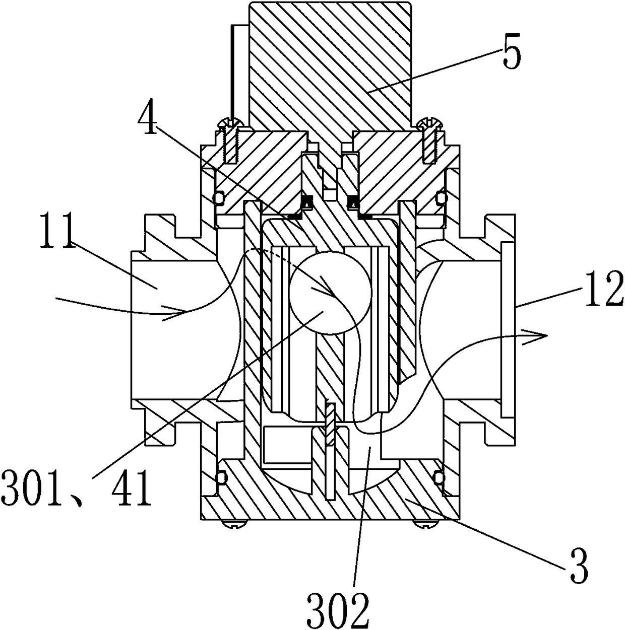
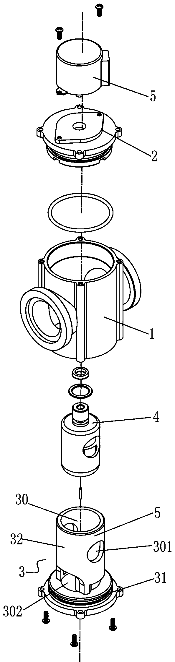
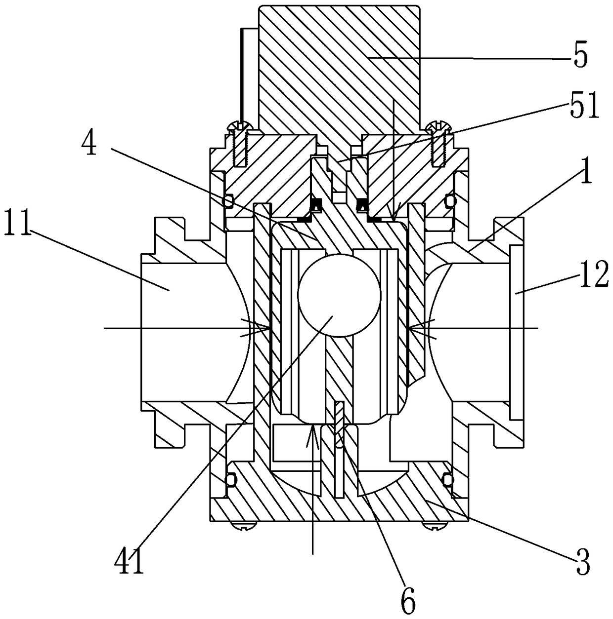
[0038] Specific implementation methods, such as Figure 1 to Figure 4 As shown, the buffer suspension flow regulating device described in the present invention mainly includes the following components: body 1, cover body 2, base 3, water control unit 4 and motor 5;

[0039] When assembling, first, a shaft body 6 is installed at the bottom of the water control unit 4, and the water control unit 4 equipped with the shaft body 6 is placed in the buffer chamber 30 on the base 3, and the shaft body 6 is attached to the base body 31, so that the water control unit 4 can be rotated and fitted in the buffer cavity 30, and through its rotation, the flow regulating hole 41 of the water control unit 4 is superimposed or dislocated with the water passing area of ​​the water inlet hole 301 on the base 3; Not only that, a certain gap is formed between the water control unit 4 and the interior of the buffer chamber 30, so that the water flow covers the entire water control unit 4;

[0040] ...


PUM


Abstract

The invention discloses a suspension flow buffering adjustment device which comprises a hollow body, a cover body and a base. The cover body and the base are integrally or separately formed on the upper side and the lower side of the body. The body is provided with a water inlet and a water outlet. The suspension flow buffering adjustment device further comprises a base and a water control unit, wherein the base comprises a buffering cavity provided with an opening, and at least two water inlet via holes and a water outlet via hole are formed in the wall of the buffering cavity. The two water inlet via holes and the water inlet are arranged in the peripheral direction in a staggered mode. The water control unit is rotatably installed in the buffering cavity through a shaft body and forms a water passing cavity with an opening corresponding to the base, and two flow adjusting holes are formed in the wall of the water passing cavity and correspond to the positions of the two flow adjusting holes. The suspension flow buffering adjustment device is simple in structure and easy to achieve, the defect that the water control unit is unbalanced in stress and is easily stuck in the rotary switching process and the like is effectively overcome. A suspension structure is adopted to minimize operating force and has a flow discharging function, the phenomenon that the body is rust and accordingly flow adjustment cannot be performed can be prevented, and the suspension flow buffering adjustment device is suitable for large-flow adjustment and easily meets the using demand.

Description

technical field [0001] The invention relates to the bathroom industry, in particular to a buffer suspension flow regulating device. Background technique [0002] At present, the existing flow regulating devices on the market include a body and a ball valve. The ball valve is controlled to rotate clockwise or counterclockwise in the body through the control end, so that the water hole of the ball valve corresponds to the water inlet and outlet on the body, and Expand or reduce the water passing area to adjust the water flow; but the existing flow regulating device has the following problems: (1) The stability of the ball valve structure is poor, because one end of the water enters and the other end is the water outlet, so that the ball valve is impacted by the water flow in the direction of the water inlet (2) The existing structure has only two parts, the body and the ball valve, and the water pressure is pressed against the outer wall of the ball valve almost instantaneousl...

Claims


Application Information

Patent Timeline
Patent Type & Authority Patents(China)
IPC IPC(8): F16K3/26F16K3/314F16K31/04F16K47/02
CPCF16K3/262F16K3/314F16K31/04F16K47/023
Inventor 林孝发林孝山李帅宇刘启乔邓小清
Owner FUJIAN XIHE SANITARY WARE TECH
Why Eureka
Try Eureka