
Cyclone incinerator

A technology of incineration device and swirling flow, which is applied to incinerators, combustion methods, combustion types, etc., can solve the problems of difficult to achieve fluidization, increase the resistance of the air distribution plate, and the materials are easy to accumulate at the bottom, so as to avoid accumulation and non-fluidization. , to ensure stable combustion and enhance the effect of disturbance

Active Publication Date: 2015-08-19
BEIJING SIWEI TIANTUO TECH CO LTD
View PDF9 Cites 6 Cited by
  • Summary
  • Abstract
  • Description
  • Claims
  • Application Information

AI Technical Summary

Problems solved by technology

However, due to the sharp shrinkage of the bottom of the furnace, the material is easy to accumulate at the bottom, which increases the resistance of the air distribution plate, and it is difficult to achieve a good fluidization. The internal rotation effect is questionable, and it is difficult to fully realize the internal and external circulation of the device as a whole.

Method used


Image

  • Cyclone incinerator
  • Cyclone incinerator

Examples


Embodiment approach

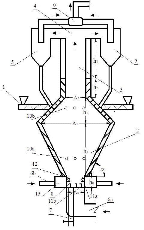
[0012] like figure 1 As shown, a cyclone incineration device includes a symmetrically arranged feeding device 1, a furnace 2, a cyclone separator 5, and the like. The top of the furnace 2 is connected to the vertical flue 3, and the top of the vertical flue 3 is arranged with an overhead flue 4, and the cyclone separator 5 is connected to the overhead flue 4, and the two sides are arranged symmetrically. Furnace 2 is wide in the middle and narrow at the upper and lower sides, and the cross-sectional area of ​​the bottom is A 0 Minimum, cross-sectional area A of the minimum upper part 2 >A 0 , the cross-sectional area A at the widest point in the middle 1 is the bottom cross-sectional area A 0 2 to 4 times that of the furnace, so as to ensure that the furnace 2 has enough internal rotation space, and reduce material elutriation.

[0013] The inner wall of the furnace 2 is covered with refractory materials, and the height of the section from the air distribution plate 11 to...


PUM


Abstract

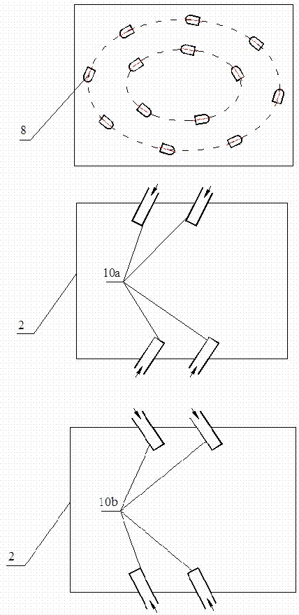
A cyclone incinerator comprises feeders symmetrically disposed, a hearth, a vertical flue connected above the hearth, an overhead flue disposed at the top of the vertical flue, and cyclone separators symmetrically disposed on two sides of the overhead flue. The hearth has wide middle and narrow top and bottom; the inner wall of the hearth is covered with refractory material; the vertical flue above the hearth is partially covered with refractory material; the bottom of the hearth is provided with a lateral primary air area, a lateral primary air distribution system and a primary air distribution system which uses directional hoods; the upper portion of the hearth is provided with an upper secondary air pipe, and the lower portion thereof is provided with a lower secondary air pipe; the horizontal rotational direction of air blown by a nozzle of the lower secondary air pipe is opposite to the rotational direction of the air blown by the nozzles of the directional air hoods; the horizontal rotational direction of the air blown by a nozzle the upper secondary air pipe is same as the rotational direction of the air blown by the nozzles of the directional air hoods. The cyclone incinerator has the advantages that materials are separated by internal circulation of cyclone grade-separation, lateral air distribution and bottom air distribution help greatly enhance flowing of the materials at the bottom, depositing of the materials is avoided, the flowing and combusting effect is excellent.

Description

technical field [0001] The invention relates to a swirling flow incineration device, which is used for incinerating wastes with low calorific value. Background technique [0002] Circulating fluidized bed is also favored in waste treatment because of its wide fuel adaptability and high combustion efficiency. However, the simple external circulation combustion equipment has a huge furnace structure and high initial investment. However, simple internal circulation combustion equipment is often complex in structure. In order to solve this problem, "A Variable Cross-section Circulating Fluidized Bed Combustion Equipment" (CN1305074A) proposed a shrinking combustion equipment with a hearth similar to a gourd. The co-rotating effect of the primary air and the secondary air strengthens the internal rotation effect of the air distribution, achieving both internal and external circulation. However, due to the sharp shrinkage of the bottom of the furnace, the material is easy to ac...

Claims


Application Information

Patent Timeline
Patent Type & Authority Applications(China)
IPC IPC(8): F23G5/30F23G5/44
CPCF23G5/30F23G5/44
Inventor 蒙爱红
Owner BEIJING SIWEI TIANTUO TECH CO LTD
Learn More