
Efficient return air furnace

A return air furnace, high-efficiency technology, applied in household furnaces/stoves, furnaces/stoves with hot water devices, household heating, etc., can solve the problem that fuel heat cannot be fully utilized and high-temperature waste heat cannot be fully utilized , Furnace seat temperature rise is not obvious and other problems, to achieve the effect of simple structure, high recycling efficiency, and reduce energy consumption

Inactive Publication Date: 2015-08-19
苏州福利恒电子科技有限公司
View PDF7 Cites 1 Cited by
  • Summary
  • Abstract
  • Description
  • Claims
  • Application Information

AI Technical Summary

Problems solved by technology

The exhaust port is generally set on the upper part of the furnace body, which prevents the heat generated by the fuel from being fully utilized
Moreover, during the fuel combustion process, the temperature of the furnace body and the furnace surface increases greatly, but the temperature increase of the entire furnace base is not obvious. Moreover, although there are some boiler flue gas waste heat recovery devices, the current boiler flue gas waste heat recovery The utilization device is not good enough in recovering low-grade flue gas waste heat, and cannot make full use of these high-temperature waste heat. At the same time, there are problems of corrosion and low recovery efficiency.

Method used


Image

  • Efficient return air furnace
  • Efficient return air furnace
  • Efficient return air furnace

Examples


Embodiment Construction

[0016] The following will clearly and completely describe the technical solutions in the embodiments of the present invention with reference to the accompanying drawings in the embodiments of the present invention. Obviously, the described embodiments are only some, not all, embodiments of the present invention. Based on the embodiments of the present invention, all other embodiments obtained by persons of ordinary skill in the art without making creative efforts belong to the protection scope of the present invention.

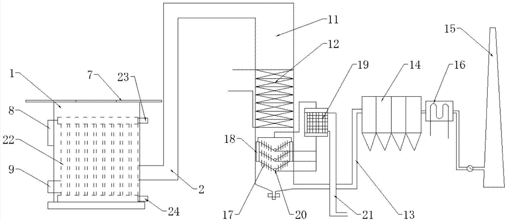
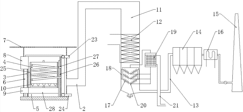
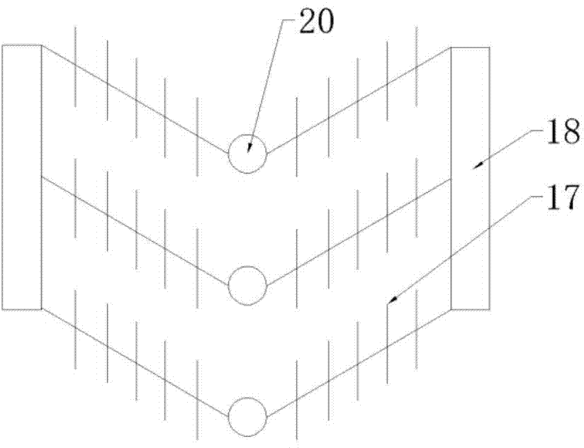
[0017] see Figure 1~3 , in an embodiment of the present invention, a high-efficiency return air furnace, including a furnace shell 1, a smoke pipe 2, a boiler tail flue 11, a multi-stage air preheater 12 placed in the boiler tail flue 11, and a smoke exhaust channel 13 , the dust remover 14 that is arranged on the smoke exhaust passage 13 and the chimney 15 that is arranged behind the dust remover 14 and communicates with the smoke exhaust passage 13, the fur...


PUM


Abstract

The invention discloses an efficient return air furnace which comprises a furnace shell, a smoke pipe, a boiler tail smoke flue, a multi-stage air preheater arranged in the boil tail smoke flue, a discharge flue, a dust remover arranged on the discharge flue and a chimney arranged in the rear of the dust remover and is communicated with the discharge flue. A furnace body is arranged in the furnace shell, a hearth and an ash chamber are arranged in the furnace body, a packing port is arranged in the hearth, an ash hole is arranged in the ash chamber, and a grate is arranged between the hearth and the ash chamber. The efficient return air furnace is simple and reasonable in structure, cooking, heating and baking are integrated, convenience in use is achieved, a cavity is arranged between the furnace shell and the furnace body, a hot water pipe is arranged on the outer side of the furnace body, the water pipe can be heated by the hearth, generated flue gas flows upwardly to flow out through the smoke pipe via the cavity, the hot water pipe can be heated secondarily through the flue gas, a spiral water pipe is further arranged in the hearth, heat of the hearth and flue gas waste heat can be effectively utilized, and heat utilization rate is increased.

Description

technical field [0001] The invention relates to the technical field of boiler equipment, in particular to a high-efficiency return air furnace. Background technique [0002] At present, for the stoves used in most of our families, the temperature around the stove rises from bottom to top after the fire is fired, and part of the heat generated by the fuel is discharged through the exhaust port. The exhaust port is generally arranged on the upper part of the furnace body, which prevents the heat generated by the fuel from being fully utilized. Moreover, during the fuel combustion process, the temperature of the furnace body and the furnace surface increases greatly, but the temperature increase of the entire furnace base is not obvious. Moreover, although there are some boiler flue gas waste heat recovery devices, the current boiler flue gas waste heat recovery The utilization device is not good enough in recovering low-grade flue gas waste heat, and cannot make full use of t...

Claims


Application Information

Patent Timeline
Patent Type & Authority Applications(China)
IPC IPC(8): F24B1/183F24B1/191
Inventor 不公告发明人
Owner 苏州福利恒电子科技有限公司
Learn More