
Thermally-driven stirling cryocooler

A refrigerator and heat-driven technology, applied in refrigerators, hot gas variable displacement engine devices, refrigeration and liquefaction, etc., can solve problems such as difficult design and processing, system vibration, unfavorable practical application, etc., to reduce design and processing Difficulty, vibration reduction effect

Active Publication Date: 2015-08-19
TECHNICAL INST OF PHYSICS & CHEMISTRY - CHINESE ACAD OF SCI
View PDF8 Cites 16 Cited by
  • Summary
  • Abstract
  • Description
  • Claims
  • Application Information

AI Technical Summary

Problems solved by technology

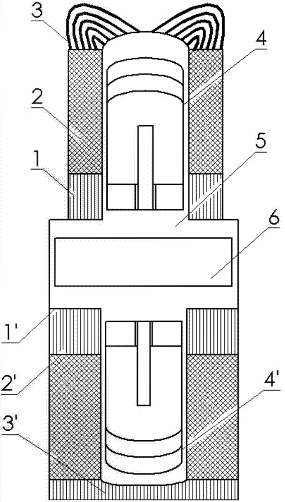
Similarly, one end of the ejector 4' of the refrigerator is at a low temperature, and the other end is located at the end of the second room temperature heat exchanger 1'. There is also a gap seal, and the design and processing are very difficult.
In addition, the discharge movement will also cause system vibration, which is not conducive to practical application.

Method used


Image

  • Thermally-driven stirling cryocooler
  • Thermally-driven stirling cryocooler
  • Thermally-driven stirling cryocooler

Examples


Embodiment 1

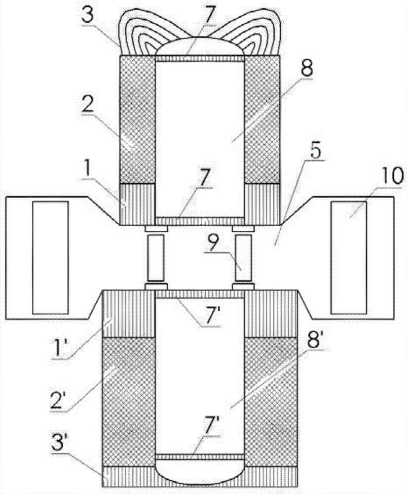
[0030] Such as figure 2 As shown, a heat-driven Stirling refrigerator provided by the present invention includes a motor, a refrigerator, an ejector and a vibrator, and the motor includes a hot end heat exchanger 3 connected sequentially from top to bottom, a first circuit The heat exchanger 2 and the first room temperature heat exchanger 1, the refrigerator includes a second room temperature heat exchanger 1', a second heat regenerator 2' and a cold end heat exchanger 3' connected in sequence from top to bottom, so The engine is provided with a first heat buffer chamber 8, the refrigerator is provided with a second heat buffer chamber 8', and the upper end of the first heat buffer chamber 8 is connected to the hot end heat exchanger 3 , the lower end of which is connected to the first room temperature heat exchanger 1 for transitioning the high temperature state at the end of the hot end heat exchanger 3 to room temperature; the lower end of the second thermal buffer chamber...

Embodiment 2

[0035] Such as Figure 4 As shown, the difference between the second embodiment and the first embodiment is that the resonator 6 can be replaced by a linear motor, and the cavity 5 is respectively provided with a linear motor on the outside of the two first piston bodies 9, so The linear motor includes a stator 12, a mover 13 and a piston 14, the stator 12 is fixedly connected to the inner wall of the cavity 5, the piston 14 is arranged at the opposite end of the mover 13 to the first piston body 9, and the mover 13 is used to drive the piston 14 to reciprocate along the stator 12. The mover 13 and the piston 14 can be used as the harmonic oscillator 6; In this embodiment, the system can output electric energy and cooling energy to the outside at the same time, which is of great practical value in occasions where electric power is scarce.

Embodiment 3

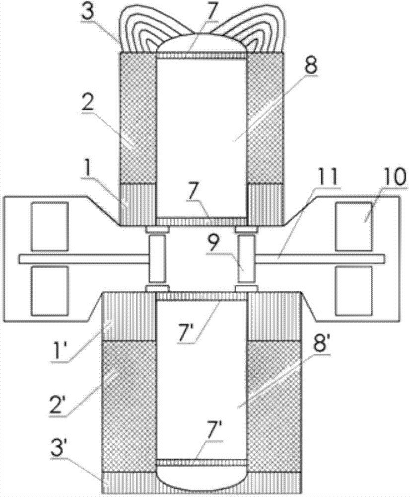
[0037] Such as image 3 As shown, the difference between the third embodiment and the first and second embodiments is that the opposite end of the first piston body 9 to the second piston body 10 or the piston 14 can be horizontally connected with a connecting rod 11, and the second piston body 10 or piston 14 are provided with the central through hole that passes described connecting rod 11, and connecting rod 11 passes central through hole, and like this, the area of ​​first piston body 9 and second piston body 10 or piston 14 two ends is different, has This helps to reduce the stiffness of the spring required to support the reciprocating movement of the second piston body 10 or piston 14.


PUM


Abstract

The invention relates to the field of a refrigerator, and discloses a thermally-driven stirling cryocooler. The thermally-driven stirling cryocooler comprises an engine, a refrigerator, a discharger and a harmonic oscillator; the engine comprises a hot end heat exchanger, a first heat accumulator and a first room temperature heat exchanger which are sequentially connected; the refrigerator comprises a second room temperature heat exchanger, a second heat accumulator and a cold end heat exchanger which are sequentially arranged, wherein the engine is internally provided with a first thermal buffering cavity, the refrigerator is internally provided with a second thermal buffering cavity, the upper end of the first thermal buffering cavity is connected with the hot end heat exchanger, and the lower end of the first thermal buffering cavity is connected with the first room temperature heat exchanger; the lower end of the second thermal buffering cavity is connected with the cold end heat exchanger, and the upper end of the second thermal buffering cavity is connected with the second room temperature heat exchanger; the engine and the refrigerator are relatively arranged up and down, a shared cavity is formed between the engine and the refrigerator, and the discharger and the harmonic oscillator are both arranged in the cavity in a contraposition way. The discharger provided by the invention can be operated at the room temperature end, the design and processing difficulty of the discharger can be reduced, and the vibration of the system can be reduced.

Description

technical field [0001] The invention relates to the technical field of refrigerators, in particular to a heat-driven Stirling refrigerator. Background technique [0002] Thermally driven low-temperature refrigerators have very good application prospects in occasions where electric energy is scarce. For example, although my country's natural gas reserves are very rich, most of them belong to unconventional natural gas such as coalbed methane and shale gas. Usually, the gas sources are scattered, the gas volume is small, and the location is remote. Traditional pipeline transportation or large-scale liquefaction equipment driven by electricity Unusable, so the utilization of these natural gas has been greatly restricted. [0003] figure 1 It is a traditional heat-driven Stirling refrigerator structure, which mainly includes three parts: a Stirling engine, a Stirling refrigerator and an oscillator, and the harmonic oscillator is located between the engine and the refrigerator. ...

Claims


Application Information

Patent Timeline
Patent Type & Authority Applications(China)
IPC IPC(8): F25B9/14F02G1/043
CPCF02G1/0435F25B9/14
Inventor 罗二仓胡剑英戴巍余国瑶吴张华张丽敏
Owner TECHNICAL INST OF PHYSICS & CHEMISTRY - CHINESE ACAD OF SCI
Learn More