

Microstrip device test system
A test system and device technology, applied in the direction of instruments, measuring electronics, measuring devices, etc., can solve the problems of insertion loss and unsatisfactory standing waves in test results, and achieve the effects of small standing waves, accurate test results, and small insertion loss
- Summary
- Abstract
- Description
- Claims
- Application Information
AI Technical Summary
Problems solved by technology
Method used
Image

Examples
Embodiment Construction
[0030] Now take the use of this system to test a circulator with microstrip transfer as an example to illustrate the use and advantages of this system.
[0031] Such as Figure 7 , Figure 8 , Figure 9 , Figure 10 , Figure 11 , Figure 12 Shown:
[0032] Vector network analyzer: On the inner conductor of the coaxial cable of the vector network analyzer, open a groove with a depth of 1mm to place the inner conductor of the stripline.
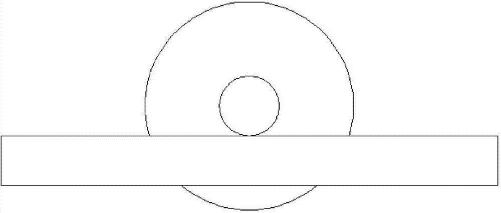
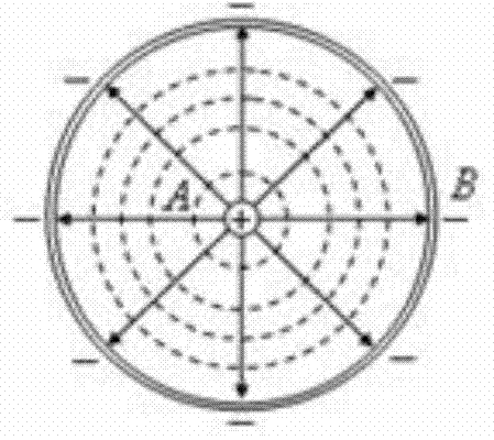
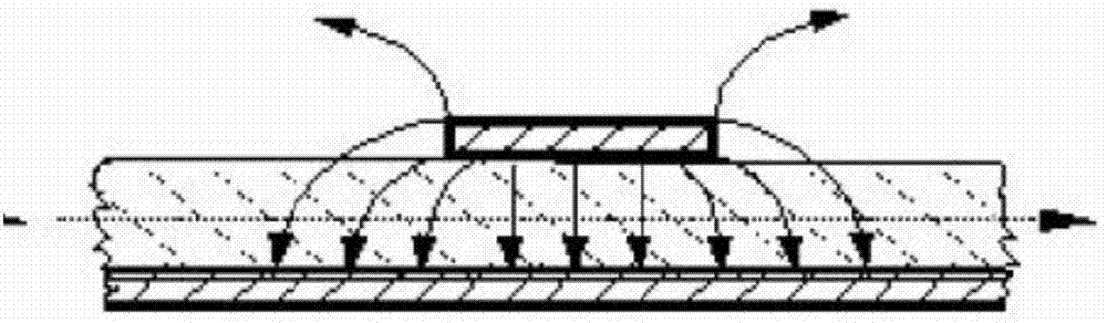
[0033] Fixture: Divided by structure, the fixture is composed of bottom plate, cover plate, medium, inner conductor and fixing screws. Divided by function, consisting of striplines and fixtures; e.g. Figure 7 , Figure 8 , Figure 9 As shown, the stripline consists of an inner conductor, two dielectric sheets, and metal parts in contact with the dielectric, and is located between the cover plate and the bottom plate. Metal extending from either side of the stripline, screw holes, and bar slots form the fixture for attaching to the s...
PUM
 Abstract
Description
Claims
Application Information