ANSYS and ADAMS-based large-scale antenna dynamical modeling method

A dynamic modeling and antenna technology, which is applied in special data processing applications, instruments, electrical digital data processing, etc., can solve the problems that the accuracy needs to be verified, it is not suitable for the design stage, and it cannot meet the requirements.

Inactive Publication Date: 2015-08-19
XIDIAN UNIV
View PDF5 Cites 18 Cited by
  • Summary
  • Abstract
  • Description
  • Claims
  • Application Information

AI Technical Summary

Problems solved by technology

Through the study of the above method, the disadvantages are summarized as follows: (1) For a simple structure, its mass and stiffness matrix can be directly obtained, and it is feasible to carry out structural dynamic modeling according to the above method
The elastic vibration is mainly described by the modal coordinates in the modal space, and there are two main methods for the rigid body motion of the antenna: (1) only the influence of inertia is considered for the rigid body motion, and the external damping is completely ignored, W.Gawronski and J.A. Mellstrom, "Elevation Control System Model for the DSS 13antenna" [J], Ground Antennas and Facilities Engineering Section, TDA Progress Report 42-106, May 15, 1991, 83-85. Will move with a constant acceleration, contrary to reality; (2) Estimating damping through simulation, Zhang Jie, Huang Jin, Song Ruixue, Qiu Lili A control-oriented large-scale antenna modeling method, 2013, (201310496650.5) Xi'an Electronic Technology University, but this estimation needs to use the actual value of the antenna, which is only applicable after the antenna is built, not in the design stage
Moreover, the above two processing methods, for the rigid body motion and elastic vibration of the antenna, are finally linearly superimposed to obtain the overall motion, without considering the coupling relationship between the two motions
But in practice, for such a complex object as the reflector antenna, the accuracy of modeling based on the idea of ​​linear superposition is yet to be verified.
Especially when the pointing accuracy of the antenna is very high, in the order of arc seconds, this modeling method often cannot meet the requirements
[0005] In summary, there is currently no dynamic description method that considers the coupling of the rigid body displacement and elastic deformation of the radar antenna at the same time to achieve its overall dynamic description

Method used


Image

  • ANSYS and ADAMS-based large-scale antenna dynamical modeling method
  • ANSYS and ADAMS-based large-scale antenna dynamical modeling method
  • ANSYS and ADAMS-based large-scale antenna dynamical modeling method

Examples


Embodiment Construction

[0049] The present invention will be further described below in conjunction with the accompanying drawings. It should be noted that this embodiment is based on the technical solution, and provides detailed implementation and specific operation process, but the protection scope of the present invention is not limited to the present invention. Example.

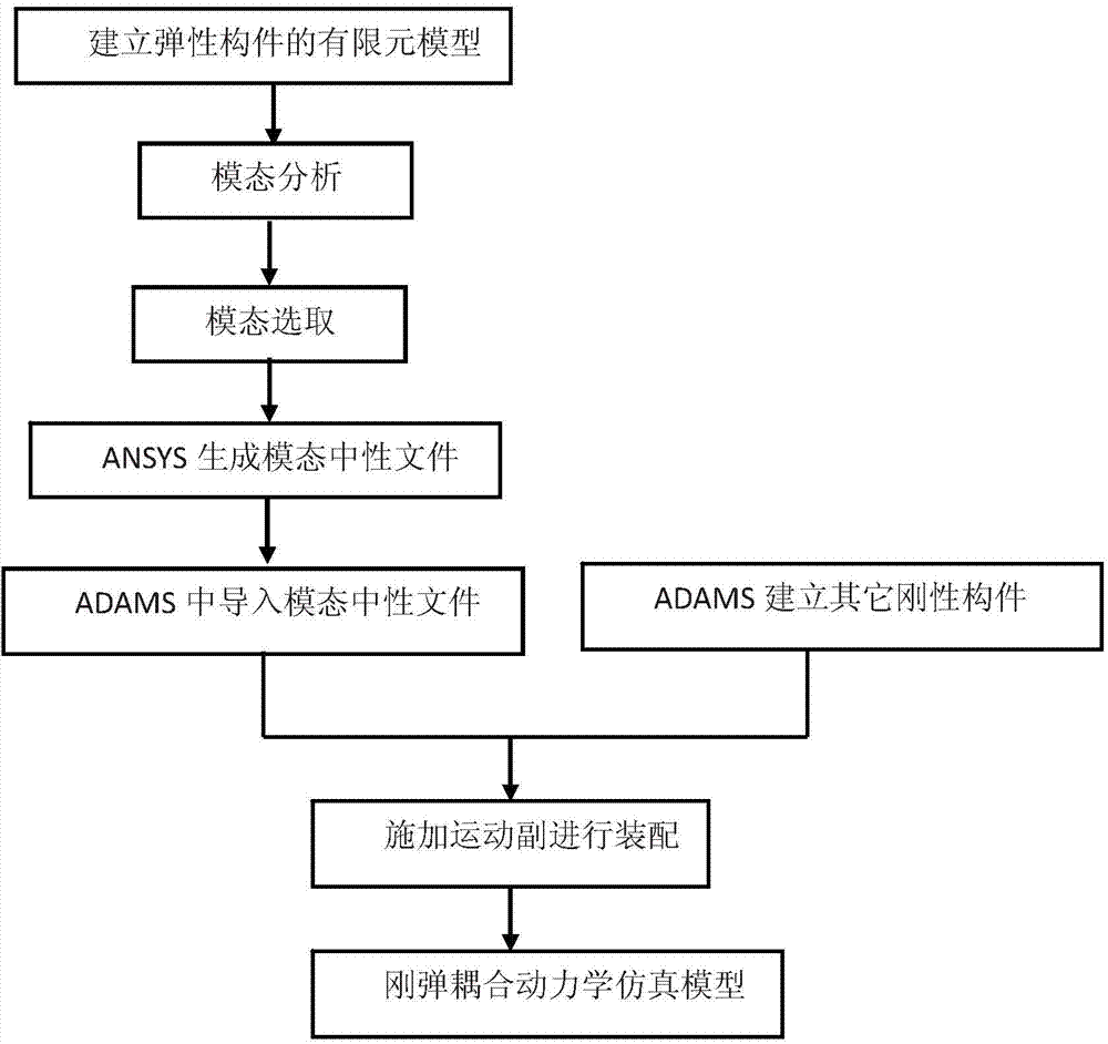
[0050] Such as figure 1 As shown, the large-scale antenna dynamics modeling method based on ANSYS and ADAMS includes the following steps:

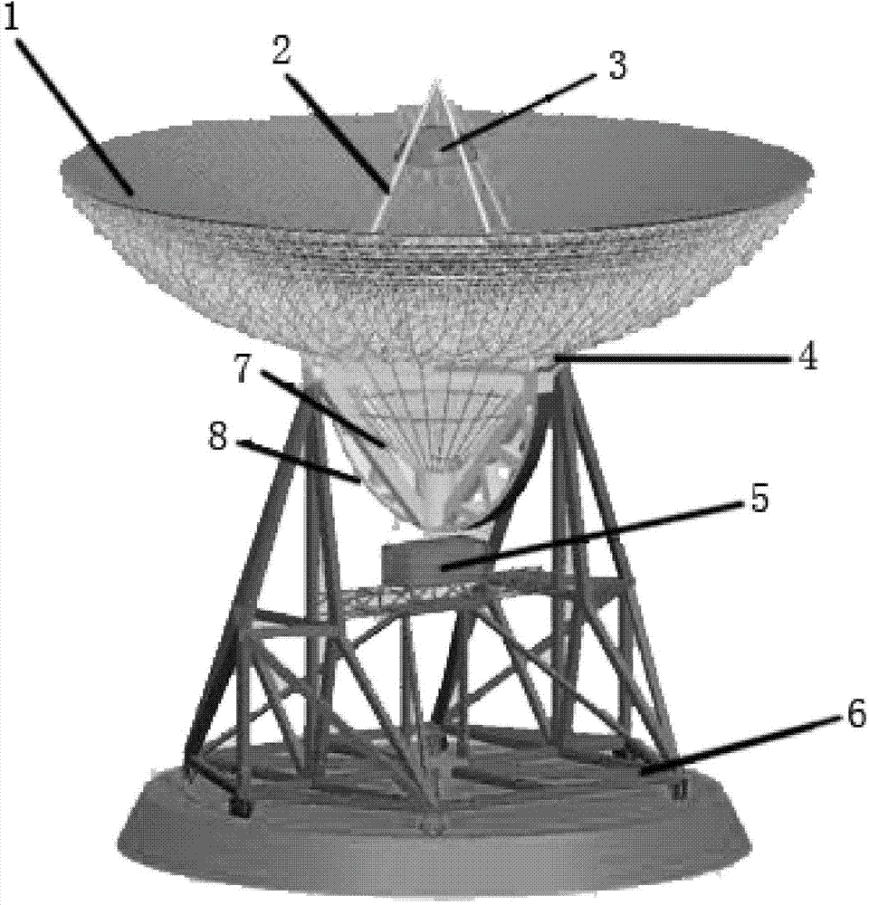
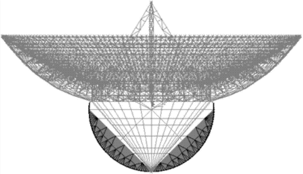
[0051] S1 Aiming at the specific structural requirements of the reflector antenna servo system, combined with ANSYS software to establish the finite element model of the elastic components of the antenna, including the reflector, secondary surface support, center body, main reflector back frame structure, umbrella support and large gear, The number of nodes in the finite element model is n d ;

[0052] S2 imposes boundary conditions on the finite element model in step S1. The boundary con...


PUM


Abstract

The invention discloses an ANSYS and ADAMS-based large-scale antenna dynamical modeling method, and mainly solves the problem that the existing modeling method cannot be used for accurately describing rigid motion of an antenna and cannot consider the problem of rigid-elastic coupling in a movement process of the antenna. The modeling method comprises the steps: based on a finite element model of an elastic component of a large reflector antenna, according to a modal analysis result, selecting the modality with the maximal contribution to antenna output, replacing node coordinates with a small quantity of modal coordinates to condense the degree of freedom of elastic deformation, and then exporting a corresponding modal neutral file; by establishing the rigid component of the antenna in ADAMS, combining the modal neutral file describing an elastomer, and performing assembly to obtain the dynamical simulation model describing the integral movement of the antenna. The ANSYS and ADAMS-based large-scale antenna dynamical modeling method overcomes the defects of the traditional modeling method, and a development period can be obviously shortened.

Description

technical field [0001] The invention belongs to the technical field of antennas, in particular to a large-scale antenna dynamic modeling method based on ANSYS and ADAMS, which is used to guide the design of a large-scale reflector antenna servo system. Background technique [0002] As the most commonly used type of high-gain microwave and millimeter-wave antennas, reflector antennas have been widely used in space communication, deep space exploration, radio astronomy and other fields by generating pencil-shaped beams to radiate energy in a directional manner. In order to more effectively explore some unknown areas and capture information from far and infinite space, reflector antennas inevitably tend to have larger apertures and higher operating frequencies. As the antenna aperture increases and the frequency increases, the beam width corresponding to the target will become narrower. If the accuracy of the narrow beam pointing to the target is not within the allowable range,...

Claims


Application Information

Patent Timeline
Patent Type & Authority Applications(China)
IPC IPC(8): G06F17/50
Inventor 李素兰魏雪梅保宏王从思冯树飞许谦项斌斌
Owner XIDIAN UNIV
Why Eureka
Try Eureka