

Magnetic core applied to reactor and reactor
A reactor and magnetic core technology, applied in the direction of transformer/inductor magnetic core, inductance with magnetic core, magnetic core/magnetic yoke, etc. High saturation magnetic flux density and other problems, to achieve the effect of reducing winding eddy current loss, reducing core eddy current loss, and large saturation current
- Summary
- Abstract
- Description
- Claims
- Application Information
AI Technical Summary
Problems solved by technology
Method used
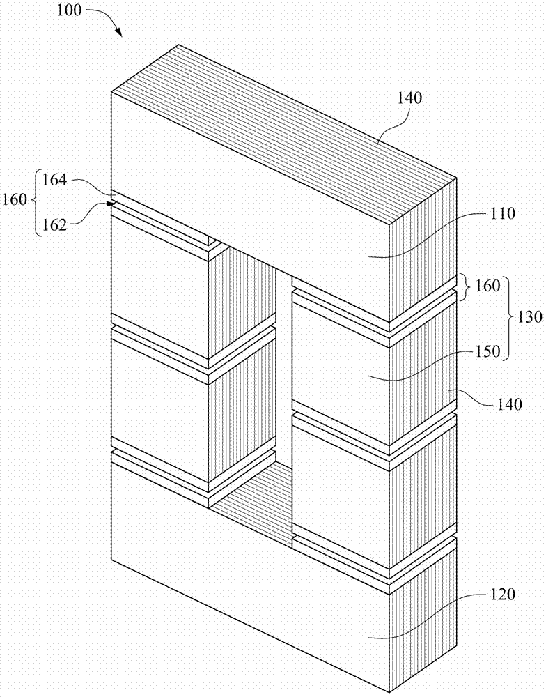
Image

Examples
experiment example 1
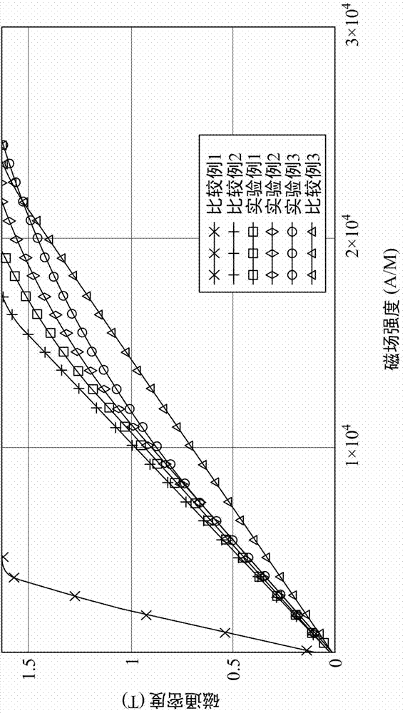
[0058] The saturation characteristics of Experimental Example 1 and Experimental Example 2 are closer to Comparative Example 2 at light load, and closer to Comparative Example 1 at heavy load. Similarly, the saturation characteristics of Experimental Example 5, Experimental Example 6, and Experimental Example 7 are closer to Comparative Example 4 at light loads, and closer to Comparative Example 3 at heavy loads. The experimental results confirm that the magnetic core can indeed obtain a more balanced performance of light and heavy load inductance values.
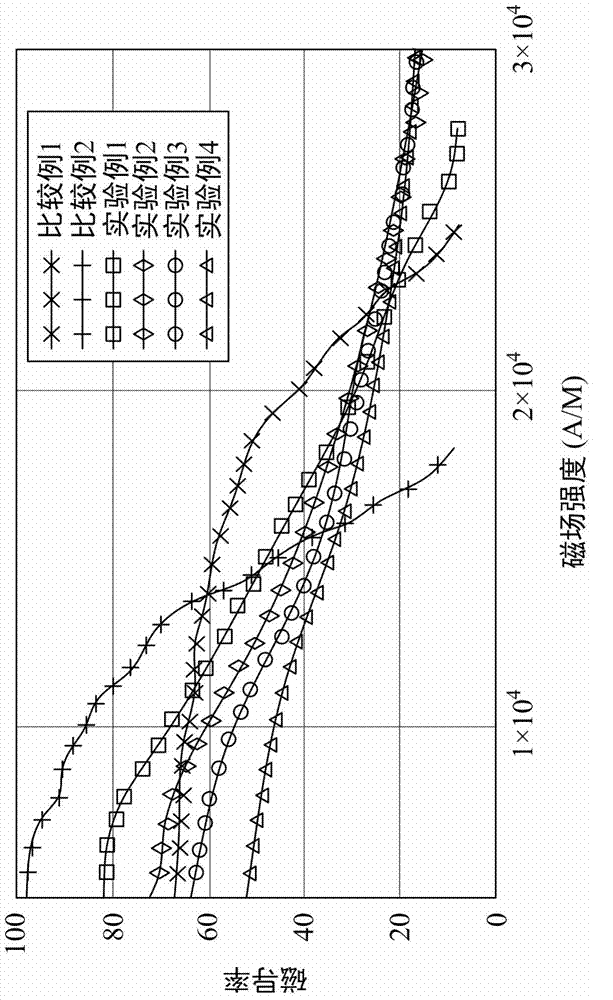
[0059] However, the volume of the balanced magnetic unit inserted in the magnetic core of the mixed material is not as large as possible. image 3 and Figure 4 It can be seen from the figure that, relative to the air gap, the insertion of too much balanced magnetic unit, such as Experiment 4 and Experiment 8, will make the saturation curve more gentle, but because the initial magnetic permeability of the core is too large...
PUM
| Property | Measurement | Unit |
|---|---|---|
| electrical resistance | aaaaa | aaaaa |
Abstract
Description
Claims
Application Information