Medium loading resonator

A dielectric loading and resonator technology, applied in the direction of resonators, waveguide devices, electrical components, etc., can solve the problems of reduced production efficiency, increased product scrap rate, unusable, etc., and achieve simplified structure, reduced production costs, and improved The effect of production efficiency

Active Publication Date: 2015-08-19
武汉凡谷陶瓷材料有限公司
View PDF5 Cites 7 Cited by
  • Summary
  • Abstract
  • Description
  • Claims
  • Application Information

AI Technical Summary

Problems solved by technology

[0004] 1. In order to accurately position the loading medium on the metal resonator rod, the bottom of the ring-shaped loading medium needs to be recessed to form a very thin side wall. However, this thin wall is easy to crack during the production process of green body pressing and ceramic sintering. The product scrap rate has increased significantly
[0005] 2. Both ends of the loading medium need to be metallized, usually both ends are covered with silver, and the most economical and effective way to be silvered is screen printing. Because the bottom is uneven, this process cannot be used, and only other methods such as spraying can be used for production, resulting in Reduced production efficiency and consequently increased costs
[0006] 3. The no-load Q value of the medium-loaded resonator is very sensitive to conductive materials. Whether it is supported and positioned by wrapping the metal resonator rod from the periphery of the loaded medium or going deep into its inner hole, it will make the medium-loaded resonator unaffected. The load Q value is greatly reduced
[0007] Therefore, existing dielectrically loaded resonators cannot be promoted on products

Method used


Image

  • Medium loading resonator
  • Medium loading resonator
  • Medium loading resonator

Examples


Embodiment Construction

[0028] The technical solutions in the embodiments of the present invention will be clearly and completely described below in conjunction with the drawings in the embodiments of the present invention.

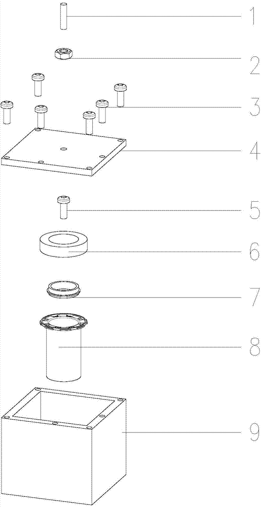
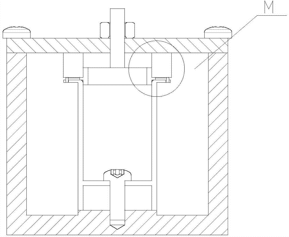
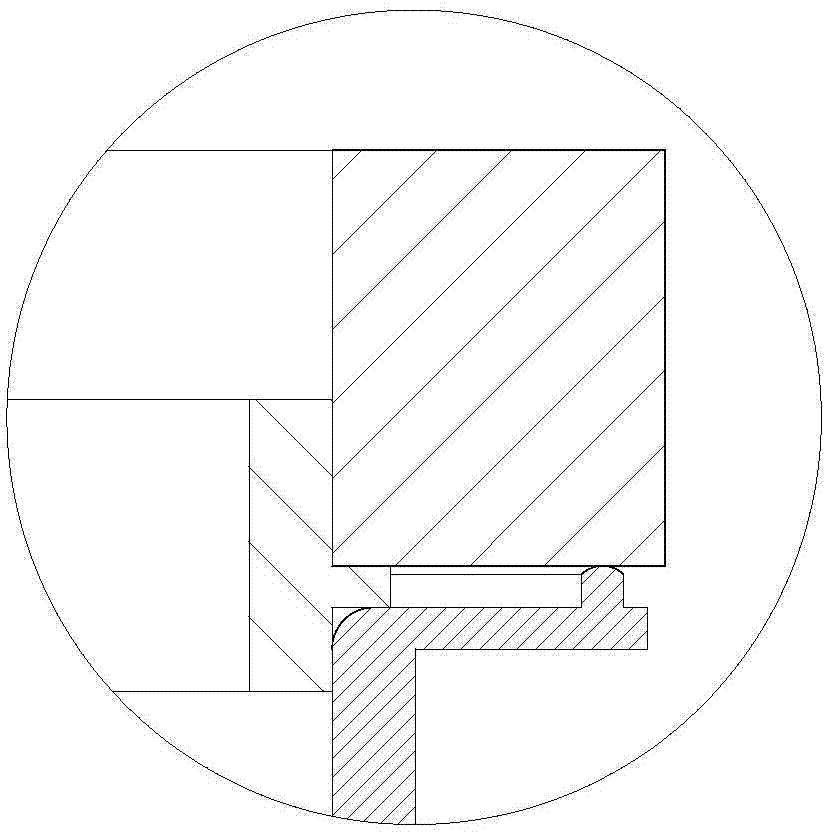
[0029] see figure 1 , figure 2 , This embodiment relates to a dielectric-loaded resonator, including a tuning screw 1 , a nut 2 , an assembly screw 3 , a cover plate 4 , a connecting screw 5 , a loading medium 6 , a positioning seat 7 , a metal resonator rod 8 and a metal cavity 9 . The tuning screw 1 is installed on the cover plate 4 through the nut 2 , the cover plate 4 is located on the metal cavity 9 , and the metal resonant rod 8 is fixed on the bottom of the metal cavity 9 . The positioning seat 7 is arranged between the lower end surface of the loading medium 6 and the top of the metal resonant rod 8 , and the connection between the positioning seat 7 and the top of the metal resonant rod 8 is conducted through an elastic metal piece.

[0030] Wherein, the loading medi...


PUM


Abstract

The invention discloses a medium loading resonator. The medium loading resonator comprises a cover plate, a tuning screw rod, a loading medium, a metal resonance rod and a metal chamber, wherein the metal resonance rod is fixed at the bottom of the metal chamber, the tuning screw rod is installed on the cover plat, the cover plate is disposed at the upper surface of the metal resonance chamber, and a cylindrical positioning seat which is provided with a ring of bosses along the circumference direction of the outer surface and is made of a nonconductive material is arranged between the metal resonance rod and the loading medium; the loading medium is made of cylindrical microwave ceramics, and the positioning seat positions the loading medium and the metal resonance rod for fixation; and the metal resonance rod is provided with an elastic metal disc, and the upper end and the lower end of the loading medium are respectively in close contact with the cover plate and the metal disc. According to the invention, since the loading medium and the metal resonance rod are positioned for fixation by use of the positioning seat, the structure of the loading medium is simplified to be a cylindrical loading medium without a side wall, the first pass yield of a product is effectively improved, at the same time, the production efficiency can be substantially enhanced, and the market competitiveness of the product is greatly improved.

Description

technical field [0001] The invention relates to a passive antenna feeder device in the field of wireless network communication, in particular to a medium-loaded resonator. Background technique [0002] For a long time, filters have played an extremely important role in the processing of electronic signals. It has the function of filtering signals of used frequencies and suppressing interference signals. With the rapid development of microwave wireless communication, miniaturized base stations have become the mainstream, and more and more stringent requirements have been placed on the volume of filters. Traditional metal coaxial resonator filters can no longer meet these requirements, so we want to use metal The open-circuit end of the coaxial resonator is loaded with high dielectric constant microwave ceramics, and the loading capacitance is increased to improve the performance of the filter while reducing its volume. [0003] There are various practical difficulties in the...

Claims


Application Information

Patent Timeline
Patent Type & Authority Applications(China)
IPC IPC(8): H01P7/10
Inventor 孟庆南钟伟刚
Owner 武汉凡谷陶瓷材料有限公司
Why Eureka
Try Eureka