Line differential protection method based on differential output of electronic current transformer

A current transformer and line differential technology, applied in the direction of emergency protection circuit devices, electrical components, etc., can solve the problems of limiting the protection action speed, increasing the energy supply burden of the high-voltage side, and phase deviation.

Inactive Publication Date: 2015-08-19
STATE GRID JIBEI ELECTRIC POWER CO LTD TANGSHAN POWER SUPPLY CO +1
View PDF2 Cites 10 Cited by
  • Summary
  • Abstract
  • Description
  • Claims
  • Application Information

AI Technical Summary

Problems solved by technology

[0003] In recent years, electronic current transformers based on Rogowski coils have been gradually put into practical use, but since the output signal of the sensor head is the differential of the measured current, in order to restore the original signal, an additional integral module needs to be added, which will inevitably increase the high voltage side data processing time, resulting in a certain time delay and phase shift, thereby limiting the action speed of protection, reducing reliability, and increasing the energy supply burden on the high voltage side

Method used


Image

  • Line differential protection method based on differential output of electronic current transformer
  • Line differential protection method based on differential output of electronic current transformer
  • Line differential protection method based on differential output of electronic current transformer

Examples


Embodiment Construction

[0051] The present invention will be further described below in conjunction with accompanying drawing.

[0052] A line differential protection method based on the differential output of an electronic current transformer, the implementation steps of the method are as follows:

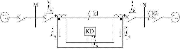
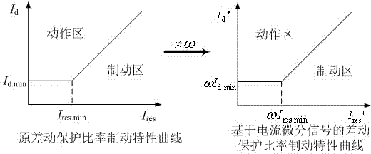
[0053] Step 1: Through the data acquisition system on the high-voltage side of the electronic current transformer installed at both ends of the transmission line, directly obtain the current differential signal output by the Rogowski coil sensor head of the electronic current transformer and :

[0054] ,in, , are the actual measured current (primary value) at the M terminal and N terminal of the line respectively, , are the measured current differential signals (secondary value) output by the electronic current transformer sensing head at the M-terminal and N-terminal of the line respectively, is the transformation ratio coefficient of the electronic current transformer, t for time; ...


PUM


Abstract

The invention provides a line differential protection method based on differential output of an electronic current transformer, and belongs to the field of power system relay protection. The technical scheme is that an integration element in high-voltage side data processing of conventional line differential protection is removed, and differential signals output by the sensing head of a Rogowski coil are directly used to realize longitudinal differential protection of a high-tension transmission line, and complexity of a device is reduced, and data processing time is reduced. On the basis of ensuring reliability and speed, adverse effect caused by an extra integral circuit is prevented, the method adapts to differential output of the Rogowski coil. PSCAD/EMTDC simulation experiments show that the differential protection scheme based on the current differential signals is effective and feasible, line rapid differential protection can be realized by directly using the differential signals output by the electronic current transformer, the integration element is removed. The method adapts to requirements of interfaces of the electronic current transformer, and can be used for main protection of high-tension transmission lines.

Description

technical field [0001] The invention relates to a line differential protection method based on the differential output of an electronic current transformer, which belongs to the field of relay protection of electric power systems. Background technique [0002] With the development of the power industry, the required power transmission capacity continues to increase, and the operating voltage level is also getting higher and higher. Due to the inherent problems of iron core saturation, residual magnetism, and ferromagnetic resonance, traditional electromagnetic transformers are increasingly difficult to meet the growing needs of power systems. The application of electronic transformers will completely solve these problems. Electronic transformers have all the functions of traditional transformers, and have the benefits of not being affected by saturation and ferromagnetic resonance. They have good insulation performance, wide frequency bandwidth, large dynamic range, small si...

Claims


Application Information

Patent Timeline
Patent Type & Authority Applications(China)
IPC IPC(8): H02H7/26
Inventor 陈学伟王伟李欢王宇翔王钦王娜李耐心李征杜鹏王华飞李爱民张剑飞李锦锦冬大龙杨联宇田新成杨鸿宏徐小华郝秋雯郝秋刚
Owner STATE GRID JIBEI ELECTRIC POWER CO LTD TANGSHAN POWER SUPPLY CO
Why Eureka
Try Eureka