Video coding method and apparatus
A video coding and sub-video technology, applied in the field of video coding methods and devices, capable of solving problems such as poor video image quality
- Summary
- Abstract
- Description
- Claims
- Application Information
AI Technical Summary
Problems solved by technology
Method used
Image
Examples
Embodiment 1
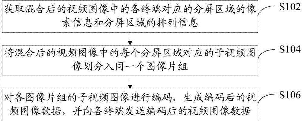
[0018] refer to figure 2 , shows a flow chart of steps of a video encoding method according to an embodiment of the present invention.
[0019] The video coding method of the present embodiment includes the following steps:
[0020] Step S102: Obtain the pixel information of the split-screen area corresponding to each terminal in the mixed video image and the arrangement information of the split-screen area.
[0021] Wherein, the pixel information of the split-screen area includes: the pixel value of the width of the split-screen area and the pixel value of the height of the split-screen area; For example, the mixed video image contains four split-screen areas, the first split-screen area is on the left side of the second split-screen area, the third split-screen area is below the first split-screen area, and the fourth split-screen area is The screen area is below the second split screen area and on the right side of the third split screen area.
[0022] It should be note...
Embodiment 2
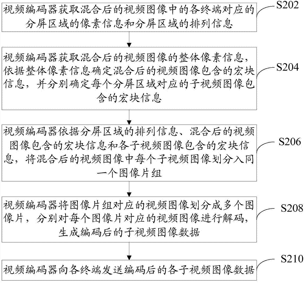
[0030] refer to image 3 , shows a flow chart of steps of a video encoding method according to Embodiment 2 of the present invention.
[0031] The video encoding method of this embodiment specifically includes the following steps:
[0032] Step S202: The video encoder obtains the pixel information of the split-screen area corresponding to each terminal in the mixed video image and the arrangement information of the split-screen area.
[0033] The video encoder in this embodiment may be an H.264 video encoder, or any other applicable type of video encoder.
[0034] Both the basic grade and the extended grade of the H.264 video encoder support the FMO (Flexible Macroblock Ordering, flexible macroblock ordering) video image division method. This video image division method uses the macroblock allocation mapping technology to allocate the macroblocks in the video image. into different slice groups, the video encoder can independently decode the video images in each slice group. ...
Embodiment 3
[0057] refer to Figure 4 , shows a flow chart of steps of a video encoding method according to Embodiment 3 of the present invention.
[0058] In this embodiment, the pixel information of the split-screen area corresponding to each terminal in the obtained mixed video image and the arrangement information of the split-screen area are used to generate a sequence parameter set, and the mixed video image is divided according to the sequence parameter set. The sub-video images corresponding to each split-screen area are divided into the same image slice group as an example to describe the video encoding method in this embodiment.
[0059] The video coding method of the present embodiment includes the following steps:
[0060] Step S302: The video encoder obtains the pixel information of the split-screen area corresponding to each terminal in the mixed video image and the arrangement information of the split-screen area.
[0061] Step S304: The video encoder generates a sequence...
PUM
 Abstract
Description
Claims
Application Information
 - R&D
- Intellectual Property
- Life Sciences
- Materials
- Tech Scout
- Unparalleled Data Quality
- Higher Quality Content
- 60% Fewer Hallucinations
Browse by: Latest US Patents, China's latest patents, Technical Efficacy Thesaurus, Application Domain, Technology Topic, Popular Technical Reports.
© 2025 PatSnap. All rights reserved.Legal|Privacy policy|Modern Slavery Act Transparency Statement|Sitemap|About US| Contact US: help@patsnap.com


