Treatment device
A therapeutic equipment, ultrasonic technology, applied in the fields of therapy, ultrasonic therapy, medical science, etc., can solve the problems of easy deflection of the probe, reduced visibility of the tip of the probe, changes in the vibration characteristics of the probe, etc.
- Summary
- Abstract
- Description
- Claims
- Application Information
AI Technical Summary
Problems solved by technology
Method used
Image

Examples
no. 1 Embodiment approach
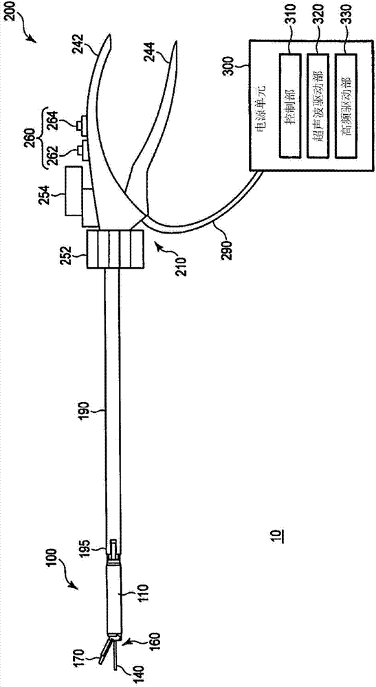
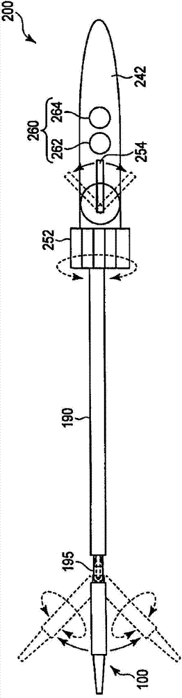
[0024] A first embodiment of the present invention will be described with reference to the drawings. The outline of the processing device 10 of this embodiment is shown in figure 1 middle. As shown in the figure, the processing device 10 includes a processing unit 100 , a shaft 190 , an operation unit 200 , and a power supply unit 300 . For convenience of description below, the treatment part 100 side is referred to as the distal end side, and the operation part 200 side is referred to as the proximal end side. exist figure 1 In , the processing part 100, the shaft 190, and the operating part 200 are shown in side views. A top view of the treatment unit 100, the shaft 190 and the operation unit 200 is shown in figure 2 middle.
[0025] The treatment device 10 of this embodiment is used, for example, in endoscopic surgery. The treatment part 100 and the shaft 190 are inserted into the abdominal cavity, for example, through a small hole cut in the abdominal wall of the su...
no. 2 Embodiment approach
[0062] A second embodiment of the present invention will be described. Here, differences from the first embodiment will be described, and the same parts will be given the same reference numerals and their descriptions will be omitted. The shapes of the ultrasonic transmission member 135 and the like in this embodiment are shown in Figure 13 and Figure 14 middle. Figure 13 It is a perspective view showing the shape of the ultrasonic transmission member 135, etc., Figure 14 It is a front view of the ultrasonic transmission member 135 and the like viewed from the distal end side. As shown in these figures, the probe 140 of the treatment part of this embodiment is formed in the shape of a square prism. Here, will Figure 13 The length of the probe 140 in the load direction indicated by the arrow in , is defined as the height h, and the length in the direction perpendicular to the load direction and the central axis is defined as the width b. At this time, the section mom...
no. 3 Embodiment approach
[0066] A third embodiment of the present invention will be described. Here, differences from the first embodiment will be described, and the same parts will be given the same reference numerals and their descriptions will be omitted. The shapes of the ultrasonic transmission member 135 and the like in this embodiment are shown in Figure 15 and Figure 16 middle. Figure 15 It is a perspective view showing the shape of the ultrasonic transmission member 135, etc., Figure 16 It is a front view of the ultrasonic transmission member 135 and the like viewed from the distal end side. As shown in these figures, the probe 140 serving as the treatment unit in this embodiment is formed in a hollow cylindrical shape. In addition, in the present embodiment, the transmission part is also formed in a cylindrical shape.
[0067] Let the outer diameter of the cylindrical shape of the treatment part be D 1 , set the inner diameter to d 1 . In addition, let the outer diameter of the t...
PUM
 Abstract
Description
Claims
Application Information
 - R&D
- Intellectual Property
- Life Sciences
- Materials
- Tech Scout
- Unparalleled Data Quality
- Higher Quality Content
- 60% Fewer Hallucinations
Browse by: Latest US Patents, China's latest patents, Technical Efficacy Thesaurus, Application Domain, Technology Topic, Popular Technical Reports.
© 2025 PatSnap. All rights reserved.Legal|Privacy policy|Modern Slavery Act Transparency Statement|Sitemap|About US| Contact US: help@patsnap.com