Turbine for a continuous-flow power plant

A generator and turbine technology, applied in the field of underwater mobile generators and wind power generators, can solve laborious problems, achieve high robustness, eliminate braking systems, and reduce production costs

Inactive Publication Date: 2015-08-19
VOITH PATENT GMBH
View PDF9 Cites 1 Cited by
  • Summary
  • Abstract
  • Description
  • Claims
  • Application Information

AI Technical Summary

Problems solved by technology

Because the twisting or adjusting mechanism is herm

Method used


Image

  • Turbine for a continuous-flow power plant
  • Turbine for a continuous-flow power plant
  • Turbine for a continuous-flow power plant

Examples


Embodiment Construction

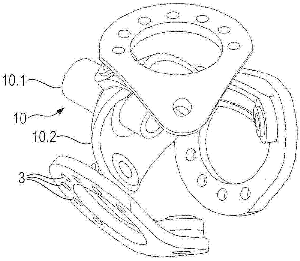
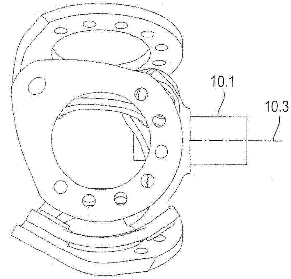
[0034] figure 1 The most important parts of the blades for adjusting the turbine (not shown) are illustrated. The central component is the adjustment body 10 . The adjustment body 10 has approximately a cup shape. It contains a drive pin 10.1 and a spherical housing 10.2.

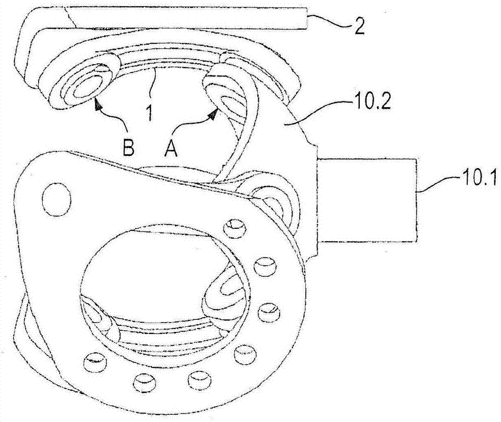
[0035] Three guide bar chains are connected to the spherical housing 10.2. In the current case, they are exactly the same. However, deviations from this are also possible. Each guide bar chain contains two guide bars. The configuration of the three guide bar chains will be explained with reference to one of these guide bar chains having guide bars 1 and 2 . figure 2 The schematic guide bar 1 comprises two swivel joints, namely a first swivel joint A and a second swivel joint B. The swivel joint A creates an articulation between the adjustment body 10 and the first end of the first guide rod 1 . The first guide rod 1 may also be called a "hinge rod".

[0036] The swivel joint B is located at the se...


PUM


Abstract

The invention relates to a turbine, in particular for a continuous-flow power plant, comprising the following features: • a hub body (11) which has a shaft for transmitting the torque which is generated by the turbine to a mobile machine; • a number of turbine blades which are supported by the hub body and can be rotated about the longitudinal axes thereof; • an adjusting body (10) is provided in the interior of the hub body, designed in the manner of a spherical link chain, which adjusting body (10) runs coaxially with respect to the shaft and can be rotated about the shaft axis; • a link chain for each blade with two links (1, 2), namely a first link (1), the first end of which is articulated on the adjusting body via a rotary joint, and a second link (2), the first end of which is articulated on the second end of the first link via a rotary joint, and the second end of which is mounted on the hub body such that it can be rotated about the longitudinal axis of the relevant blade; • wherein the adjusting body comprises a drive journal (10.1) and a ball socket (10.2), and • at least the first link (1) is of spherical design as viewed in side view.

Description

technical field [0001] The invention relates to the field of flow generators. It relates in particular to underwater mobile generators, but also to wind turbines. The flow generator comprises a water turbine; a generator, which is in driving connection with said turbine; and a support structure, which stands as the most important component on the bottom of the body of water. Such flow generators are used in any kind of flowing body of water, such as rivers, but especially in oceans. For example, harnessing the energy of tidal currents. Background technique [0002] The turbine and generator are located in a torpedo-shaped housing (see DE 10 2013 001 212 and DE 10 212 025 127). The turbine, generator and casing form the so-called nacelle. US 8,109,728 B2 describes a turbine having: a hub body carrying a plurality of turbine blades; an adjustment body arranged in the hub body; and a guide bar chain for each blade . [0003] The turbine comprises a hub body carrying a plu...

Claims


Application Information

Patent Timeline
IPC IPC(8): F03B17/06F03B13/26F03D1/06
CPCF05B2210/16F03D1/0666F03B17/061Y02E10/721F05B2250/411F03B13/264Y02E10/28F05B2260/79Y02E10/72Y02E10/30F03D1/0658F03B15/06F03B3/06F03D7/0224Y02E10/20
Inventor 克里斯托夫·席克林格帕尔蒂克·海恩斯本杰明·朔依纳特
Owner VOITH PATENT GMBH
Why Eureka
Try Eureka