Tray washing machine and method

A technology for cleaning machines and trays, applied in cleaning methods and utensils, cleaning methods using liquid, chemical instruments and methods, etc. It does not meet the requirements of energy saving and environmental protection, etc., to achieve better cleaning effect, improve cleaning effect, and facilitate drainage and air drying.

Active Publication Date: 2015-08-26
YANTAI TONGNAN IND CO LTD
View PDF11 Cites 11 Cited by
  • Summary
  • Abstract
  • Description
  • Claims
  • Application Information

AI Technical Summary

Problems solved by technology

[0003] The existing plastic tray cleaning is to place the tray horizontally on the conveyor belt, and use ordinary water to clean it. The tray is placed horizontally for cleaning, and the bottom surface of the tray is in contact with the conveyor belt. It is not clean, and although the upper surface of the tray can be washed with water, because the tray is placed horizontally, the water in the storage tank cannot be drained in time and can only be cleaned by drying, resulting in unclean cleaning of the printing stains in the storage tank on the surface of the tray ;The ordinary water used for cleaning has low purity and contains minerals, impurities, etc., and water marks will appear on the cleaned tray after drying, the cleaning effect is poor, and the clea

Method used


Image

  • Tray washing machine and method
  • Tray washing machine and method
  • Tray washing machine and method

Examples


Embodiment Construction

[0048] The principles and features of the present invention are described below in conjunction with the accompanying drawings, and the examples given are only used to explain the present invention, and are not intended to limit the scope of the present invention.

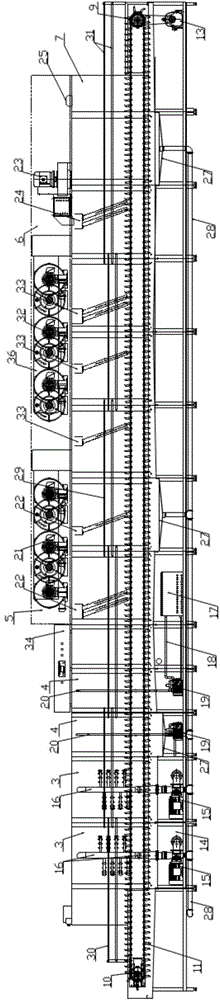
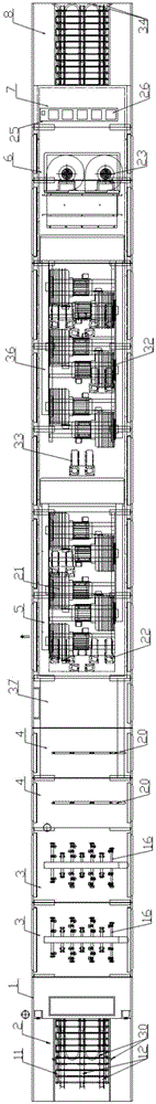
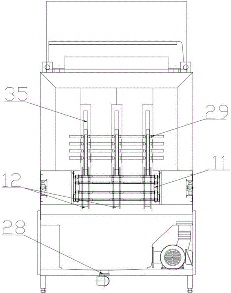
[0049] Such as Figure 1 to Figure 7 As shown, a pallet cleaning machine includes a body 1, the body 1 is a box structure, including a material conveying mechanism that runs through the inside of the body, a feeding section 2, and a water initial washing section 3 arranged in sequence from front to back , cleaning section 4, hot air shower section 5, hot air heating section 6, ion air shower section 7 and discharge section 8;

[0050] The material conveying mechanism includes a driving roller 9, a driven roller 10 and a conveying chain 11 surrounding the driving roller 9 and the driven roller 10, and the conveying chain 11 is provided with a plurality of vertically placed waiting The conveying card position 12 of t...


PUM


Abstract

The invention discloses a tray washing machine. The tray washing machine comprises a machine body. The machine body is of a box type structure. The tray washing machine further comprises a material conveying mechanism penetrating through the interior of the machine body, a feeding section, a water initial washing section, a cleaning section, a hot air blowing and spraying section, a hot air heating section, an ion air blowing and spraying section and a discharging section, wherein the feeding section, the water initial washing section, the cleaning section, the hot air blowing and spraying section, the hot air heating section, the ion air blowing and spraying section and the discharging section are sequentially distributed from front to back. The tray washing machine further comprises a tray clamping mechanism. The tray clamping mechanism comprises guide guard bars used for supporting trays. The guide guard bars are installed on the two sides of the portion above the conveying clamping position. The two ends of the guide guard bars are fixedly supported on the machine body. The invention further discloses a tray washing method. The tray washing method includes the following steps: tray arranging, water initial washing, cleaning, hot air blowing and spraying, cold air blowing and spraying, hot air heating, ion air blowing and spraying, discharging and inspecting. By means of the tray washing machine and method, the washing efficiency is improved, the washing effect is improved, the tray washing quality is guaranteed, the washing cost is reduced, the washed trays can be recycled, and energy is saved.

Description

technical field [0001] The invention relates to a cleaning machine and a cleaning method, in particular to a tray cleaning machine and a cleaning method, and belongs to the technical field of blister tray processing. Background technique [0002] With the rapid development of electronic product technology in today's world, the replacement cycle of electronic products is becoming more and more frequent. While updating electronic products, electronic merchants also put forward higher requirements for the performance of products, especially the requirements for cleanliness. The higher the temperature, the more clean and dust-free the plastic trays for holding electronic products such as mobile phone products. [0003] The existing plastic tray cleaning is to place the tray horizontally on the conveyor belt, and use ordinary water to clean it. The tray is placed horizontally for cleaning, and the bottom surface of the tray is in contact with the conveyor belt. It is not clean, ...

Claims


Application Information

Patent Timeline
IPC IPC(8): B08B3/02B08B3/08B08B13/00B08B7/04
CPCB08B3/022B08B3/08B08B7/04B08B13/00B08B2203/02
Inventor 施方兵
Owner YANTAI TONGNAN IND CO LTD
Why Eureka
Try Eureka