Printer with built-in hob paper cutting device

A paper cutting device, built-in technology, applied in the printing device, printing, etc., can solve the problems of blade wear, reduce the service life of the paper cutting device, increase the height or length, etc., to prolong the service life, increase the service life, reduce the The effect of small wear

Inactive Publication Date: 2015-08-26
KONG YUE ELECTRONICS & INFORMATION IND XIN HUI
View PDF11 Cites 2 Cited by
  • Summary
  • Abstract
  • Description
  • Claims
  • Application Information

AI Technical Summary

Problems solved by technology

The moving knife assembly of this type of paper cutting device is a modular structure with a rectangular parallelepiped shape. In order to achieve cutting, the moving knife assembly must be set relatively perpendicular to the paper outlet, which makes the printer equipped with the moving knife assembly Its height or length will increase significantly, which is not conducive to the design of the printer's shape and the requirements for the miniaturization of the printer
[0004] Moreover, the paper cutting device in the traditional technology is in plane contact when the movable blade and the fixed blade are in contact, which easily makes the mutual bonding force between the movable blade and the fixed blade larger, and the wear of the blade is more likely to occur, reducing the cost of the paper cutting device. service life, increasing the cost of consumables for users

Method used


Image

  • Printer with built-in hob paper cutting device
  • Printer with built-in hob paper cutting device
  • Printer with built-in hob paper cutting device

Examples


Embodiment Construction

[0026] The present invention will be described in further detail below in conjunction with the accompanying drawings and embodiments.

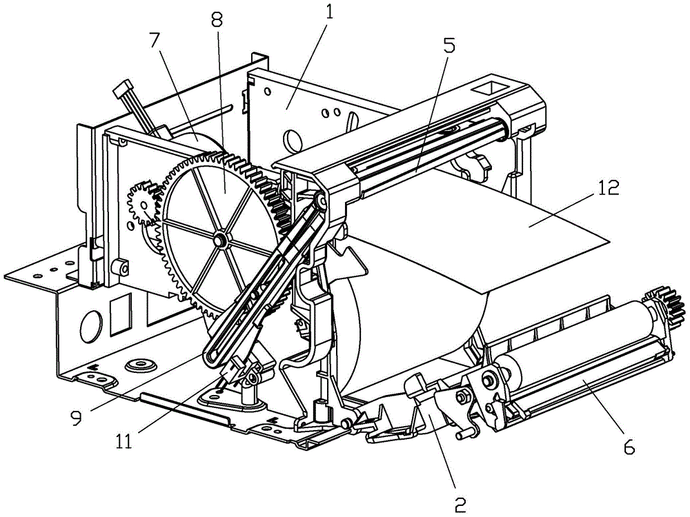
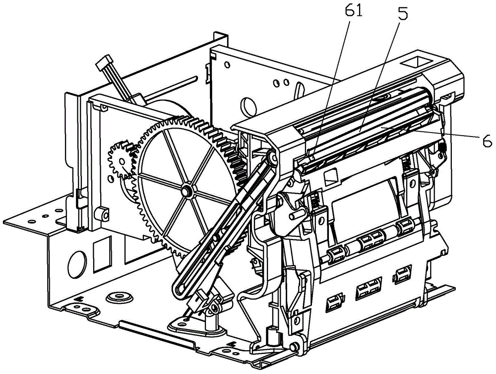
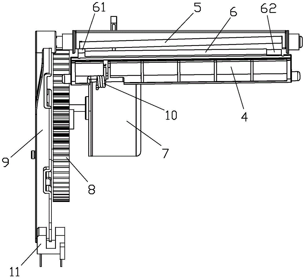
[0027] refer to Figure 1~Figure 11 , the printer with the built-in roller cutting device of the present invention includes a core assembly 1 and a paper-feeding roller fixing frame assembly 2 connected to the core assembly 1, and the core assembly 1 and the paper-feeding roller fixing frame The component 2 is pivotally connected with a moving knife fixing frame 3 and a fixed knife fixing frame 4 respectively, and the moving knife fixing frame 3 and the fixed knife fixing frame 4 are provided with a moving blade 5 and a fixed blade 6 respectively. A drive motor 7 and a cutter gear 8 driven by the drive motor 7 are arranged on the top, and a cutter drive arm 9 that is driven by the cutter gear 8 and can swing back and forth is connected to the cutter gear 8. In this embodiment, the following Structure: A rivet 81 is provided on the side end su...


PUM


Abstract

The invention discloses a printer with a built-in hob paper cutting device. The printer includes a machine core assembly and a paper feeding roller fixing frame assembly which are pivoted with a moving blade fixing frame and a fixed blade fixing frame respectively; the moving blade fixing frame and the fixed blade fixing frame are provided with a moving blade and a fixed blade respectively; the machine core assembly is provided with a stepping motor and a cutter gear driven by the stepping motor; the cutter gear is connected with a cutter driving arm which is driven by the cutter gear so as to swing in a reciprocating manner; one end of the cutter driving arm is fixedly connected with the moving blade fixing frame so as to drive the moving blade to move in a reciprocating manner; the fixed blade is provided with a guide arm used for guiding the moving blade; the paper feeding roller fixing frame assembly is provided with a torsional spring used for driving the fixed blade to rotate towards the moving blade; the two cutting edges of the moving blade and the fixed blade are arranged obliquely in a manner that the closer the two cutting edges are to the guide arm, the smaller the interval between the cutting edges is; and the cutting edge of the moving blade is a plane curve. The printer of the invention is simple and compact in structure. The appearance design and miniaturization design of the printer can be benefitted, and the service life of the paper cutting device is long.

Description

technical field [0001] The invention relates to a printer, in particular to a printer with a built-in roller cutter paper cutting device. Background technique [0002] With the rapid development of modern society, printers have been widely used in various industries such as supermarkets, banks, convenience stores, postal services, etc. In view of people's continuous requirements for automation and intelligence, general printers must have the function of automatic paper cutting. [0003] The paper cutting device inside the existing printer includes a fixed blade and a movable blade. When the two blades overlap in the thickness direction or when the two blades are perpendicular to each other, the movable blade is driven forward by a DC motor to extend forward, so that the movable blade intersects the fixed blade. Performs a scissor-like type of cut. The moving knife assembly of this type of paper cutting device is a modular structure with a rectangular parallelepiped shape. I...

Claims


Application Information

Patent Timeline
Patent Type & Authority Applications(China)
IPC IPC(8): B41J11/70
Inventor 黎家杰梁钊伟梁岐江
Owner KONG YUE ELECTRONICS & INFORMATION IND XIN HUI
Why Eureka
Try Eureka