Air foot adopting direct air supply and provided with throttling nozzles and single floating plate

A throttle and gas foot technology, applied in the field of gas foot, can solve the problems of inconvenient replacement of the throttle nozzle and complicated structure of the gas foot, and achieve the effects of improving maintenance efficiency and adaptability, reducing the difficulty of processing and assembly, and shortening the development cycle.

Active Publication Date: 2015-08-26
HARBIN INST OF TECH
View PDF8 Cites 4 Cited by
  • Summary
  • Abstract
  • Description
  • Claims
  • Application Information

AI Technical Summary

Problems solved by technology

[0005] The purpose of the present invention is to solve the problems of complex structure of the existing air foot and inconvenient replacement of the throttle nozzle, and to provide a gas foot directly supplied by the throttle nozzle with a single floating plate

Method used


Image

  • Air foot adopting direct air supply and provided with throttling nozzles and single floating plate
  • Air foot adopting direct air supply and provided with throttling nozzles and single floating plate
  • Air foot adopting direct air supply and provided with throttling nozzles and single floating plate

Examples


specific Embodiment approach 1

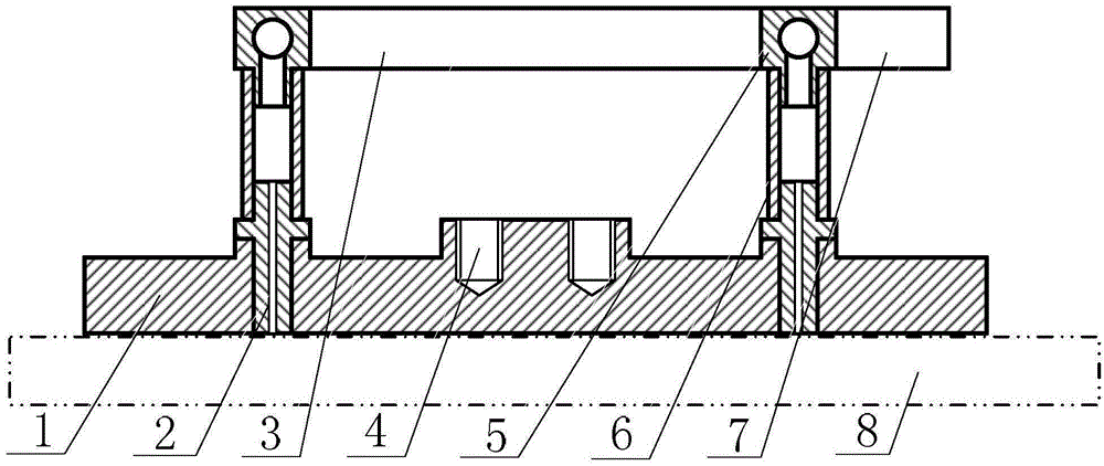
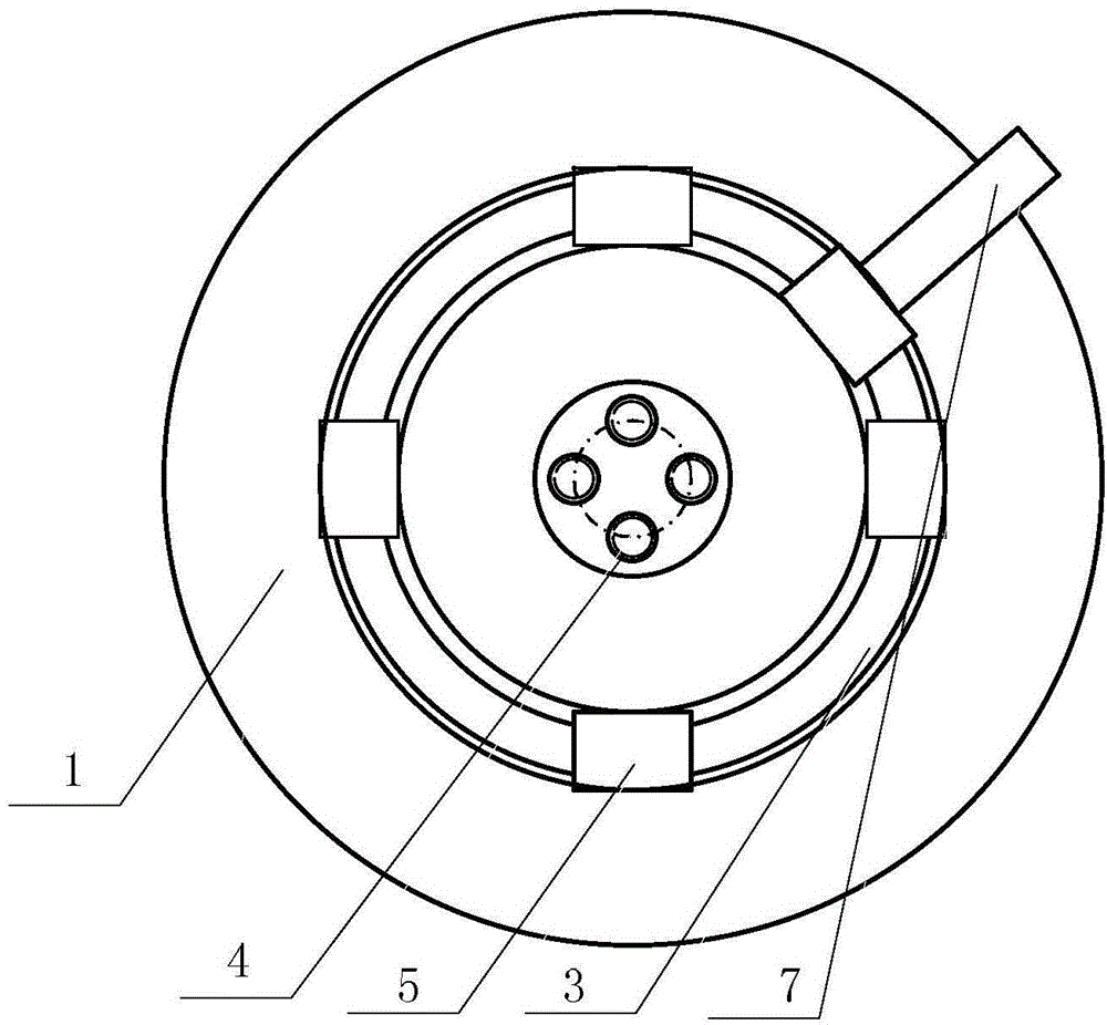
[0016] Specific implementation mode one: the following combination figure 1 and figure 2 Describe this embodiment, the throttle nozzle directly supplies air to the single floating plate air foot in this embodiment, which includes the air foot base plate 1, the throttle nozzle 2, the annular air supply pipe 3, the fastening connection hole 4, the quick connection tee 5, Throttle nozzle air supply pipe 6 and intake pipe 7,

[0017] The air foot base plate 1 is arranged in cooperation with the air flotation platform 8. On the air foot base plate 1, N threaded holes are evenly arranged along the circumferential direction in the middle of the radial direction, and N is an integer greater than or equal to 3. Each threaded hole corresponds to Install a throttle nozzle 2, each throttle nozzle 2 is correspondingly inserted into the head end of a throttle nozzle air supply pipe 6, and the end of each throttle nozzle air supply pipe 6 communicates with the annular air supply pipe 3 th...

specific Embodiment approach 2

[0022] Specific implementation mode two: the following combination figure 1 Describe this embodiment, this embodiment will further explain Embodiment 1, the middle section of the outer circular surface of the throttle nozzle 2 has a ring-shaped protrusion, and the ring-shaped protrusion makes the outer ring surface of the throttle nozzle 2 form a stepped surface, and the throttle nozzle 2 The stepped surface is positioned and fixed with the threaded hole and the throttle nozzle air supply pipe 6 .

[0023] The outer surface of the throttle nozzle 2 forms a stepped cylindrical structure, and its center is processed with a Φ0.1mm-0.5mm hole by precision drilling or laser drilling. The diameter of the foot and the number of orifices are designed. The throttle nozzle 2 is mounted on the air foot base plate 1 through thread fit, and the positioning is realized through the stepped surface, so as to ensure the relative position accuracy between the lower surface of the throttle noz...

specific Embodiment approach 3

[0024] Embodiment 3: This embodiment further describes Embodiment 1 or 2. A pressure regulating valve and an on-off valve are installed on the throttle nozzle air supply pipe 6 .

[0025] Installing a pressure regulating valve and an on-off valve on the throttle nozzle air supply pipe 6 can realize independent control of the throttle nozzle 2 gas supply pressure and on-off. Close the on-off valve of the blocked throttle nozzle, and the replacement of the blocked throttle nozzle can be realized without cutting off the gas.

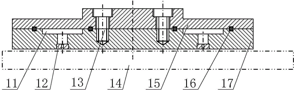
[0026] The throttle nozzle of the air foot in the present invention directly supplies air from the annular air supply pipe through the air supply pipe of the throttle nozzle, cancels the air sealing plate in the traditional air foot, reduces the sealing requirements of the air foot substrate, and thus reduces the processing and assembly At the same time, the threaded fit between the throttle nozzle and the air foot base plate is adopted, and the stepped sur...


PUM


Abstract

The invention provides an air foot adopting direct air supply and provided with throttling nozzles and a single floating plate, belongs to the technical field of the air foot, and aims to solve the problems that the conventional air foot is complex in structure and the throttling nozzles are inconvenient to replace. The air foot comprises an air foot baseplate, the throttling nozzles, annular air supply pipes, fastening connecting holes, fast connecting tee joints, throttling nozzle air supply pipes and an air inlet pipe, wherein the air foot baseplate is matched with an air-floating platform; N threaded holes are uniformly formed in the radial middle section of the air foot baseplate in the circumferential direction, N is an integer larger than or equal to 3, each throttling nozzle is correspondingly mounted in each threaded hole in a matched manner and is correspondingly inserted into the head end of each throttling nozzle air supply pipe, the tail end of each throttling nozzle air supply pipe is communicated with the corresponding annular air supply pipe through one fast connecting tee joint, and the annular air supply pipes are connected with the air inlet pipe; the multi[le fastening connecting holes are uniformly formed in the center of the upper surface of the air foot baseplate in the circumferential direction.

Description

technical field [0001] The invention relates to a single-floating plate air foot directly supplied by a throttle nozzle, and belongs to the technical field of air foot. Background technique [0002] Precision measurement, high-precision position control, weak force measurement and drive, zero-gravity environment simulation, etc. require that there is no friction between two bodies in relative motion or the friction force is as small as possible. The air suspension technology forms a high-pressure air film between the two relatively moving bodies by spraying high-pressure gas from the throttle nozzle, thereby realizing the non-contact and low-friction relative motion of the two relatively moving bodies. The relative movement of the two bodies in the plane is often realized by using the air foot, that is, the high-pressure gas is sprayed out through the throttle nozzle on the air foot, and a high-pressure air film is formed between the air foot and the air flotation platform, ...

Claims


Application Information

Patent Timeline
Patent Type & Authority Applications(China)
IPC IPC(8): F16C32/06
Inventor 刘延芳马明阳齐骥刘兴富周啟航齐乃明
Owner HARBIN INST OF TECH
Why Eureka
Try Eureka