
Conductive structure and manufacturing method thereof, array substrate and display device

A technology of conductive structure and fabrication method, applied in semiconductor/solid-state device manufacturing, circuits, electrical components, etc., can solve the problems of small protrusions, affecting the optical inspection of signal line contact conditions, etc., to reduce the continuous length and reduce the phenomenon of small protrusions Effect

Active Publication Date: 2015-08-26
BOE TECH GRP CO LTD
View PDF3 Cites 3 Cited by
  • Summary
  • Abstract
  • Description
  • Claims
  • Application Information

AI Technical Summary

Problems solved by technology

[0003] In the LTPS process, in order to reduce the line resistance, metal aluminum (Al) with low cost, high conductivity, and very small metal ion diffusion is generally used to make each signal line. However, in the subsequent Hydro (hydrogenation) process , due to the thermal expansion properties of pure aluminum itself, pure Al with a higher thickness is very prone to small protrusions (hillocks) on the surface when the grain direction is relatively consistent, which greatly affects the contact of the signal line and the subsequent optical inspection work

Method used


Image

  • Conductive structure and manufacturing method thereof, array substrate and display device
  • Conductive structure and manufacturing method thereof, array substrate and display device
  • Conductive structure and manufacturing method thereof, array substrate and display device

Examples


Embodiment Construction

[0024] The specific embodiments of the present invention will be described in further detail below in conjunction with the drawings and embodiments. The following examples are used to illustrate the present invention, but not to limit the scope of the present invention.

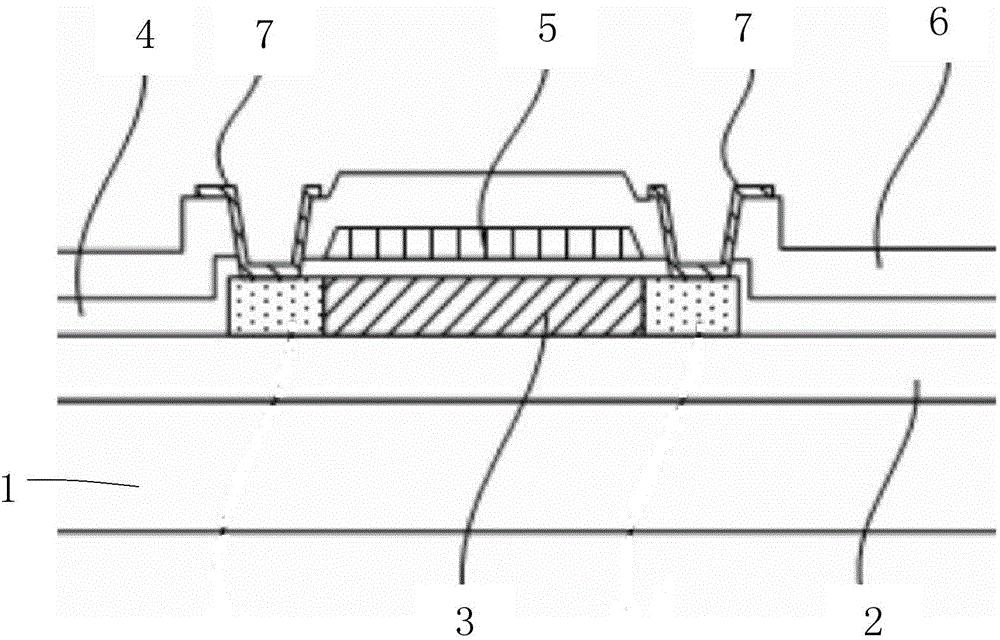
[0025] The embodiment of the present invention provides a conductive structure, which includes multiple first metal layers made of aluminum, and a second metal layer is also provided between every two adjacent first metal layers. The second metal layer is made of metal other than aluminum.

[0026] In the conductive structure provided by the embodiments of the present invention, multiple first metal layers made of aluminum are provided, and a second metal layer is provided between every two adjacent first metal layers for blocking, thereby reducing the number of single-layer first metal layers. The continuous length of the crystal grains in a metal layer can further reduce the small protrusions generated by the c...


PUM

PropertyMeasurementUnit
Thicknessaaaaaaaaaa

Abstract

The invention provides a conductive structure and a manufacturing method thereof, an array substrate and a display device. The conductive structure comprises multilayer first metal layers made of aluminum, and a second metal layer is arranged between every two adjacent first metal layers. The second metal layers are made of metal apart from aluminum. According to the conductive structure, the multilayer first metal layers made of aluminum are arranged, and the second metal layer is arranged between every two adjacent first metal layers for blocking so that continuous length of crystal grains in the single first metal layer can be reduced, and thus a small bump phenomenon of the conductive structure generated in heating can be reduced without reducing the overall thickness of the conductive structure.

Description

Technical field [0001] The present invention relates to the field of display, in particular to a conductive structure and a manufacturing method thereof, an array substrate, and a display device. Background technique [0002] Low temperature poly-silicon (LTPS) thin film transistor display devices are different from traditional amorphous silicon thin film transistor display devices, and their electron mobility can reach 50-200 cm2 / V-sec, which can effectively reduce the channel The area thus reduces the area of ​​the thin film transistor device, and achieves the purpose of increasing the aperture ratio and integration degree, thereby improving the brightness of the display while also reducing power consumption. [0003] In the LTPS process, in order to reduce the line resistance, the signal lines are generally made of aluminum (Al) with low cost, high conductivity, and very small metal ion diffusivity. However, in the subsequent Hydro (hydrogenation) process Due to the thermal exp...

Claims


Application Information

Patent Timeline
IPC IPC(8): H01L23/50H01L29/41H01L29/43H01L27/12H01L29/786H01L21/28H01L21/02
CPCH01L23/50H01L29/41H01L29/786H01L27/124H01L29/41733H01L29/4908H10K59/131H01L21/28008H01L29/42384
Inventor 田宏伟马凯葓徐文清左岳平许晓伟
Owner BOE TECH GRP CO LTD
Learn More