Battery case limiting and flanging mechanism

A technology of a battery casing and a hemming knife is applied in the directions of assembling battery machines, secondary battery manufacturing, positioning devices, etc., and can solve the problems of inconvenient use, high use and maintenance costs, complex structure, etc., and achieves simple structure, Easy operation and high production efficiency

Inactive Publication Date: 2015-08-26
白翠贞
View PDF3 Cites 0 Cited by
  • Summary
  • Abstract
  • Description
  • Claims
  • Application Information

AI Technical Summary

Problems solved by technology

The commonly used edge folding machine has a complex structure and is not designed for outsourcing edge shells, so it is not very convenient to use, and the cost of use and maintenance is relatively high.

Method used


Image

  • Battery case limiting and flanging mechanism
  • Battery case limiting and flanging mechanism

Examples


Embodiment 1

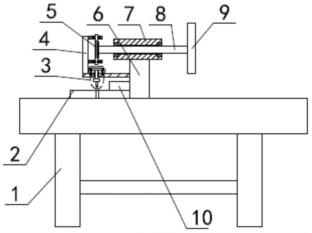
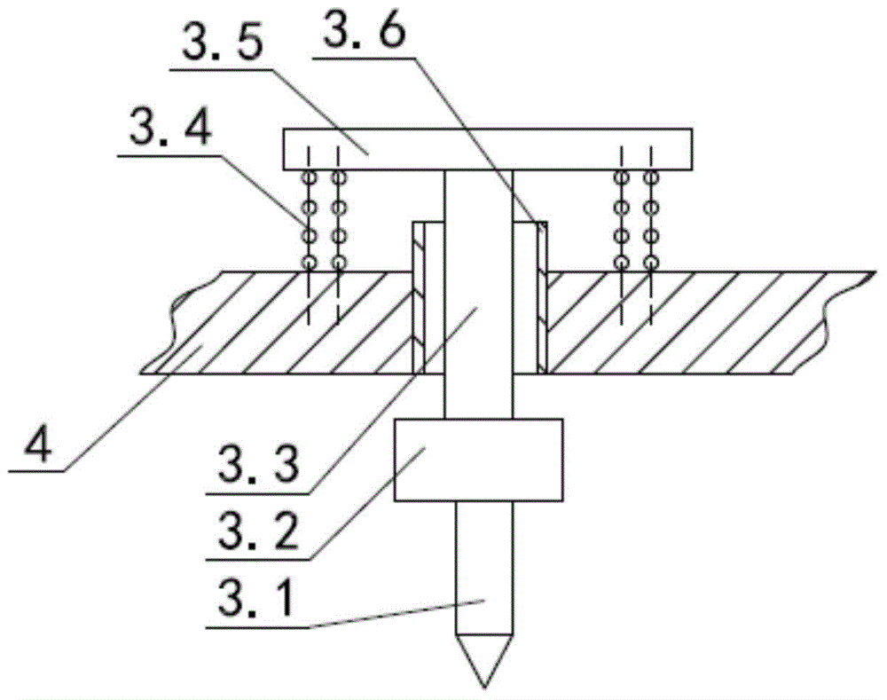
[0017] Such as figure 1 , figure 2 As shown, the battery shell limit folding mechanism includes a workbench 1, on which a bottom mold 2 for folding is installed, and a mounting post 6 is vertically fixed on the workbench 1 on the right side of the bottom mold 2. A sleeve 7 is horizontally installed on the mounting column 6, a rotating shaft 8 is horizontally installed on the sleeve 7, and a handle 9 for rotation is installed at the right end of the rotating shaft 8, and the bottom mold 2 is provided with a hemming directly above it. The folding reset mechanism 3 includes a mounting bracket 4 fixed on the mounting post 6, a folding knife 3.1 and a transmission rod 3.3 that moves up and down. The folding knife 3.1 is installed on the transmission rod 3.3 through the knife seat 3.2 At the lower end, a sliding sleeve 3.6 is sleeved on the transmission rod 3.3, and the sliding sleeve 3.6 is installed on the mounting bracket 4. The upper end of the transmission rod 3.3 is horizontal...

Embodiment 2

[0021] This embodiment is changed on the basis of the first embodiment, and the height of the worktable 1 is changed to 1000 mm. Others are the same as in Example 1.

Embodiment 3

[0023] This embodiment is changed on the basis of the first embodiment, and the height of the workbench 1 is changed to 1100 mm. Others are the same as in Example 1.


PUM

PropertyMeasurementUnit
heightaaaaaaaaaa

Abstract

The invention relates to a battery case limiting and flanging mechanism, and belongs to the technical field of battery case flanging. The battery case limiting and flanging mechanism comprises a workbench, wherein a bottom die is mounted on the workbench; a mounting column is fixedly arranged on the workbench on the right side of the bottom die; a bushing is mounted on the mounting column; a rotating shaft horizontally penetrates through the bushing; a wheel handle is mounted at the right end of the rotating shaft; a flanging reset mechanism used for flanging is correspondingly arranged right above the bottom die; the flanging reset mechanism comprises a mounting bracket, a flanging knife and a transmission rod which moves up and down; the flanging knife is mounted at the lower end of the transmission rod through a knife holder; a reset plate is fixedly arranged at the upper end of the transmission rod; springs are mounted between the reset plate and the mounting bracket and on the left and right sides of the transmission rod; a worm and gear mechanism used for power transmission is arranged between the transmission rod and the rotating shaft; and a limiting block is fixedly arranged on the bottom die on the right side of the flanging knife through a bolt. The battery case limiting and flanging mechanism is convenient to operate, and has the advantage of effectively controlling the using cost and the maintenance cost while ensuring the production efficiency.

Description

Technical field [0001] The invention relates to a limit folding mechanism for a battery shell, belonging to the technical field of battery shell folding. Background technique [0002] At present, our commonly used computer batteries, mobile phone batteries, etc., will have a thin outer side shell on the outside of the battery. During production, in order to improve production efficiency while reasonably reducing production costs, these outer side shells are contracted. The main steps of shell production are as follows: Mr. produces the unfolded surface of the outer side shell, and then folds this plane through a folding machine or manually, and finally gets the outer side shell. The commonly used folding machine has a complicated structure and is not designed for outer side shells, so it is not very convenient to use, and the use and maintenance costs are high. Summary of the invention [0003] In view of the above-mentioned problems, the present invention provides a battery shel...

Claims


Application Information

Patent Timeline
Patent Type & Authority Applications(China)
IPC IPC(8): H01M10/04
CPCB21D19/08B21D43/003H01M10/0404Y02P70/50
Inventor 赵华
Owner 白翠贞
Why Eureka
Try Eureka