
Power-stabilizing laser output device

A laser output device and a technology with stable power, applied in the field of lasers, can solve the problems of cumbersome calibration steps, large deviations between detection results and actual values, signal power drop, etc. Effect

Inactive Publication Date: 2015-08-26
JIAXING KEMIN ELECTRONICS EQUIP TECH
View PDF7 Cites 8 Cited by
  • Summary
  • Abstract
  • Description
  • Claims
  • Application Information

AI Technical Summary

Problems solved by technology

However, as the continuous operation time increases, the output power of the laser will gradually decrease, causing a decrease in signal power and affecting the stability of the instrument
[0003] To solve the problem of insufficient stability of lasers, on the one hand, instrument developers try to construct lasers with better stability. However, the main performance parameters of lasers include many indicators, and the optimization of stability performance is often accompanied by the decline of other indicators, so it is impossible to pass the laser performance. Optimization completely solves this problem
On the other hand, the instrument developer adds a correction step to the long-term use. According to the performance of the laser used, when the continuous use exceeds a certain time limit, the system test needs to be performed manually or automatically, and the test result after correction is based on it. However, the correction The steps are generally cumbersome and time-consuming, which affects the continuous use of the instrument
When the calibration interval is small, it may not be possible to detect the entire process, but when the calibration interval is large, it will cause a large deviation between some test results and the actual value, which will affect the stability of the instrument

Method used


Image

  • Power-stabilizing laser output device
  • Power-stabilizing laser output device
  • Power-stabilizing laser output device

Examples


Embodiment Construction

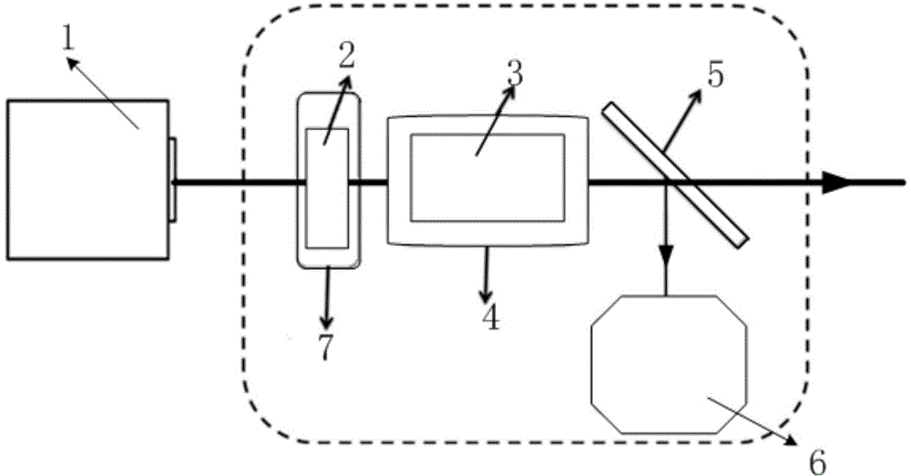
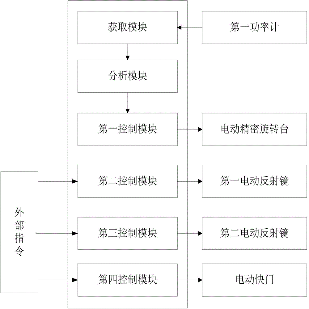
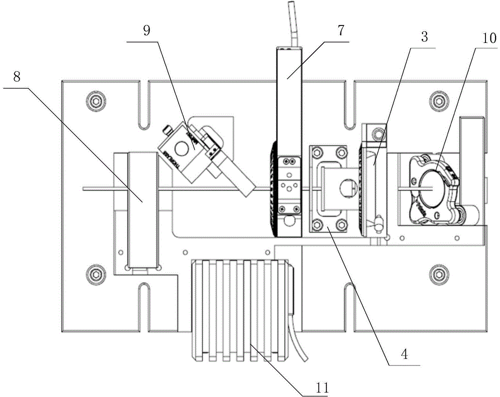
[0017] An embodiment of the present invention provides a power stable laser output device, see figure 1 and image 3 , including: motorized precision rotary stage 7, half-wave plate 2, polarizing prism 3, light barrier 4, beam splitter 5, motorized shutter 8, first power meter 6, second power meter 11, first motorized rotating mirror 9 , the second electric rotating mirror 10 and a processing unit.

[0018] see figure 1 , the half-wave plate 2 is installed on the electric precision rotary table 7, and the electric precision rotary table 7 drives the half-wave plate 2 to rotate simultaneously when the electric precision rotary table 7 rotates. When the half-wave plate 2 rotates in the forward direction, the light component of a given polarization state in the outgoing light of the half-wave plate 2 increases;

[0019] see figure 1 , the polarizing prism 3 is arranged on the rear side of the half-wave plate 2, and the light barrier 4 is fixed below the half-wave plate 2. Th...


PUM


Abstract

The invention relates to the technical field of laser, and especially relates to a power-stabilizing laser output device. The device comprises an electric precise rotary platform, a half wave plate, a polarizing prism, a light trap, a beam splitter, a first power meter, and a processing unit. The half wave plate is disposed on the electric precise rotary platform. The polarizing prism is disposed at the rear side of the half wave plate, and the light strap is fixed below the half wave plate. A laser beam passes through the half wave plate and enters into the polarizing prism. The light with a fixed polarization direction in the laser beam passes through the polarizing prism, and the light which does not pass through the polarizing prism is transmitted to the light strap for loss. The beam splitter is disposed at the rear side of the polarizing prism, and the laser beam from the polarizing prism is transmitted to the beam splitter. The processing unit is connected with the power meter and the electric precise rotary platform. The device provided by the invention reduces the power decay of the laser beam outputted by the polarizing prism till that the power of the light outputted by the polarizing prism increases target power, and guarantees the stability of the power of outputted laser.

Description

technical field [0001] The invention relates to the field of laser technology, in particular to a power-stabilized laser output device. Background technique [0002] Optical detection refers to the method of detecting various parameters of the sample by using the interaction between light and the sample. It has the advantages of non-contact, non-destructive and fast, and has been widely used in various fields. In order to enhance signal light intensity and improve detection sensitivity, high-power lasers are widely used in optical detection equipment. However, with the increase of continuous operation time, the light output power of the laser will gradually decrease, causing the signal power to decrease and affecting the stability of the instrument. [0003] To solve the problem of insufficient stability of lasers, on the one hand, instrument developers try to construct lasers with better stability. However, the main performance parameters of lasers include many indicators,...

Claims


Application Information

Patent Timeline
Patent Type & Authority Applications(China)
IPC IPC(8): H01S3/13
Inventor 陈鲁刘虹遥王安凯张朝前张学一杨乐马砚忠路鑫超
Owner JIAXING KEMIN ELECTRONICS EQUIP TECH
Learn More