Electromagnetic transmitter

A technology for electromagnetic transmitters and generator sets, which is applied in the direction of electrical components, high-efficiency power electronic conversion, and output power conversion devices, and can solve problems such as electromagnetic interference, voltage and current spikes, and increased switching losses of switching tubes.

Inactive Publication Date: 2015-08-26
BEIJING UNIV OF TECH
View PDF11 Cites 18 Cited by
  • Summary
  • Abstract
  • Description
  • Claims
  • Application Information

AI Technical Summary

Problems solved by technology

At present, the mainstream topology of electromagnetic transmitters is based on two-stage inverters, and its power part is essentially a switching power supply. Increasing the output power of the transmitter will inevitably lead to an increase in the voltage or current borne by the switching tube. If only Using ordinary pulse wi

Method used


Image

  • Electromagnetic transmitter
  • Electromagnetic transmitter
  • Electromagnetic transmitter

Examples


Embodiment Construction

[0020] Embodiments of the present invention will be described in detail below with reference to the accompanying drawings.

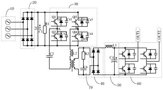
[0021] figure 1 A circuit diagram of the electromagnetic transmitter of the present invention is shown.

[0022] Such as figure 1 Shown, a kind of electromagnetic transmitter of the present invention is characterized in that, described electromagnetic transmitter comprises:

[0023] Generator set 10, three-phase rectifier bridge 20, filter capacitor C1, primary inverter bridge 30, resonant inductor L2, isolation capacitor C2, high-frequency transformer T, high-frequency rectifier bridge 40, LC filter circuit 50, and secondary inverter bridge60;

[0024] In the above circuit, the generator set 10 is connected with the three-phase rectifier bridge 20, and the generator set 10 outputs the three-phase alternating current to the input end of the three-phase rectifier bridge 20; the output end of the three-phase rectifier bridge 20 is connected with the fil...


PUM


Abstract

The invention relates to an electromagnetic transmitter. The electromagnetic transmitter comprises an electric generator set, a three-phase rectifier bridge, filter capacitors, a first level inverter bridge, a resonant inductor, an insulation value capacitor, a high-frequency transformer, a high-frequency rectifier bridge, a LC filter circuit and a second level inverter bridge. The electric generator set, the three-phase rectifier bridge, the filter capacitors, the first level inverter bridge, the high-frequency transformer, the high-frequency rectifier bridge, the LC filter circuit and the second level inverter bridge and an output port are successively connected. The resonant inductor and the insulation value capacitor are connected in series to a line between the first level inverter bridge and a primary side of the high-frequency transformer. The filter capacitors are connected in parallel to each power device of the first level inverter bridge. The filter capacitors, the resonant inductor and the insulation value capacitor form a resonance loop. By using the electromagnetic transmitter, a soft switch technology is used in the first level inverter bridge so that the voltage of the power devices of the first level inverter bridge during an on or off process is zero; zero voltage switch of the power devices is realized.

Description

technical field [0001] The present invention relates to the technical field of power rectification and inverter, in particular to an electromagnetic transmitter. Background technique [0002] The electromagnetic transmitter constructs the distribution information of the conductivity of the underground medium by obtaining the response of the earth medium to the incident electromagnetic field. Metal ores usually have good electrical conductivity, so the electromagnetic method is the most effective geophysical prospecting method for finding metal ores. [0003] With the rapid development of modern power electronics technology and devices, the topology of the main circuit of the electromagnetic transmitter is also changing. At present, the mainstream topology of electromagnetic transmitters is based on two-stage inverters, and its power part is essentially a switching power supply. Increasing the output power of the transmitter will inevitably lead to an increase in the voltage...

Claims


Application Information

Patent Timeline
IPC IPC(8): H02M5/458H02M1/08
CPCY02B70/10
Inventor 张一鸣王旭红朱学政陶海军高俊侠田甲申郑起佳
Owner BEIJING UNIV OF TECH
Why Eureka
Try Eureka