Eureka AIR delivers breakthrough ideas for toughest innovation challenges, trusted by R&D personnel around the world.

Audio electrical signal transmission line

A technology for transmission lines and electrical signals, which is applied in the circuit field of audio and electrical signal transmission lines, can solve the problems that the automatic variable resistance value of audio and electrical signal transmission lines cannot be realized, and achieve the effect of reducing adverse effects

Inactive Publication Date: 2015-08-26
刘志强
View PDF0 Cites 3 Cited by
  • Summary
  • Abstract
  • Description
  • Claims
  • Application Information

AI Technical Summary

Problems solved by technology

[0002] The known audio signal transmission line is composed of a non-photosensitive resistor with a non-automatically variable resistance and an electrical connection with a capacitor. The electrical connection of the resistor and the capacitor constitutes a circuit with many required functions, such as the output of an amplifier with signal inversion characteristics. And the input terminal constitutes a resistance-capacitance negative feedback circuit; the feedback signal with opposite polarity or opposite direction (inversion) is subtracted from the input signal at the input terminal, or the audio frequency in the line is adjusted by using a potentiometer-type variable resistance. Signal reduction processing control; because in the audio electric signal transmission line, the resistance of any form, structure and material has no amplification effect on the audio electric signal, so the signal control using resistance is described as reducing processing control, obviously, the known The resistance value of the resistor electrically connected in the audio electrical signal transmission line is fixed or needs to be changed artificially, and the automatic variable resistance value in the audio electrical signal transmission line cannot be realized to realize the adjustment and control of the audio electrical signal

Method used


Image

  • Audio electrical signal transmission line
  • Audio electrical signal transmission line

Examples


Embodiment Construction

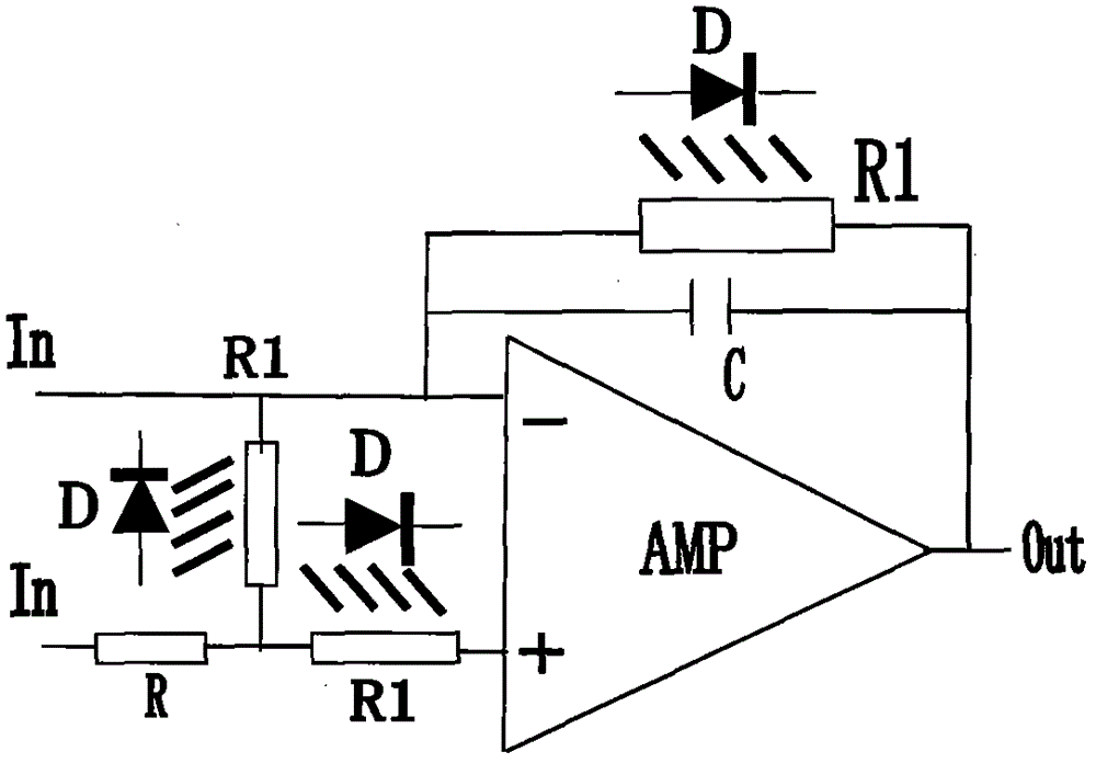
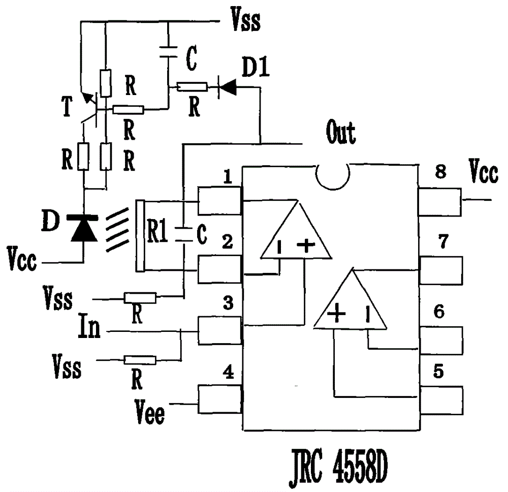
[0007] For the description of the embodiments of the present invention, please refer to the appended figure 1 , attached figure 2 , with figure 1 Express as the electrical connection principle diagram of the present invention, appended figure 1 Shown are different ways of electrically connecting and setting photoresistor R1 in the audio signal transmission line, wherein the object of the present invention can be achieved by adopting any of the ways; this embodiment adopts the dual-channel integrated operational amplifier JRC4558D as the audio signal amplifier In order to facilitate understanding, only one channel is drawn as an example. According to the technical characteristics provided by the present invention, the photosensitive resistor R1 is electrically connected to the output terminal 1 pin and the input terminal 2 pin of the audio signal transmission line of the amplifier JRC4558D, and the light The diode D and the drive amplifier T are mainly used to detect and amp...


PUM


Abstract

An audio electrical signal transmission line is mainly composed of an audio electrical signal transmission line, a photo resistor, a negative feedback circuit, an audio frequency amplifier, a light emitting diode, a driving amplifier, and relative resistors and capacitors. According to the invention, automatic change of the resistance of a variable resistor in the audio electrical signal transmission line is achieved simply with low cost, so that the voltage of an output audio signal is stabilized, and adverse effects to the audio frequency amplifier, a loudspeaker and tone quality because the signal is too large is prevented.

Description

Technical field: [0001] The invention relates to the technical field of audio circuits, in particular to the circuit technology of audio electric signal transmission lines. Background technique: [0002] The known audio signal transmission line is composed of a non-photosensitive resistor with a non-automatically variable resistance and an electrical connection with a capacitor. The electrical connection of the resistor and the capacitor constitutes a circuit with many required functions, such as the output of an amplifier with signal inversion characteristics. And the input terminal constitutes a resistance-capacitance negative feedback circuit; the feedback signal with opposite polarity or opposite direction (inversion) is subtracted from the input signal at the input terminal, or the audio frequency in the line is adjusted by using a potentiometer-type variable resistance. Signal reduction processing control; because in the audio electric signal transmission line, the res...

Claims


Application Information

Patent Timeline
Patent Type & Authority Applications(China)
IPC IPC(8): H03F1/34
Inventor 刘志强
Owner 刘志强
Why Eureka
Eureka Blog
Learn More