
Clock signal producing circuit

A technology of clock signal and generating circuit, which is applied in the field of circuits, can solve the problems of large delay errors, etc., and achieve the effects of fast recovery speed, large operating voltage range, and reduced delay errors

Active Publication Date: 2015-08-26
SG MICRO
View PDF4 Cites 11 Cited by
  • Summary
  • Abstract
  • Description
  • Claims
  • Application Information

AI Technical Summary

Problems solved by technology

[0010] The main purpose of the present invention is to provide a clock signal generation circuit, to at least solve the problem of excessive delay error of the clock signal generation circuit in the above-mentioned prior art

Method used


Image

  • Clock signal producing circuit
  • Clock signal producing circuit
  • Clock signal producing circuit

Examples


Embodiment Construction

[0030] It should be noted that, in the case of no conflict, the embodiments in the present application and the features in the embodiments can be combined with each other. The present invention will be described in detail below with reference to the accompanying drawings and examples.

[0031] In order to enable those skilled in the art to better understand the solutions of the present invention, the following will clearly and completely describe the technical solutions in the embodiments of the present invention in conjunction with the drawings in the embodiments of the present invention. Obviously, the described embodiments are only It is an embodiment of a part of the present invention, but not all embodiments. Based on the embodiments of the present invention, all other embodiments obtained by persons of ordinary skill in the art without making creative efforts shall fall within the protection scope of the present invention.

[0032] An embodiment of the present invention...


PUM


Abstract

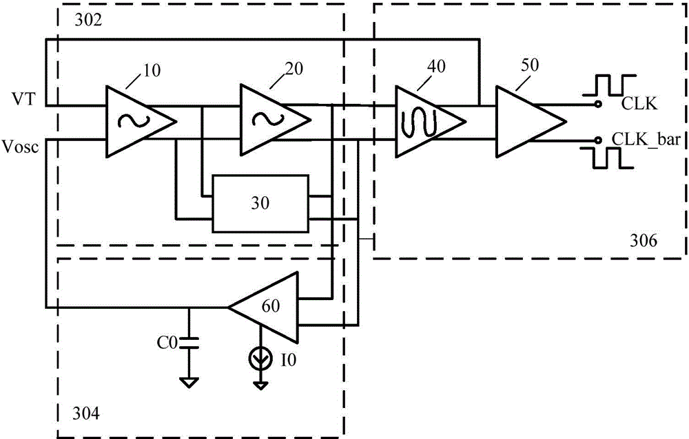
The invention provides a clock signal producing circuit. The clock signal producing circuit comprises a small signal amplification unit, a delay unit and a level shifting unit. The small signal amplification unit comprises a first input end for inputting a threshold voltage, a second input end for inputting an oscillation voltage, a first output end for outputting a first differential signal, and a second output end for outputting a second differential signal. The delay unit comprises a third input end connected with the first output end, a fourth input end connected with the second output end, a third output end for outputting the oscillation voltage to the second input end, and a capacitor with one end connected with the third output end. The level shifting unit comprises a fifth input end connected with the first output end, a sixth input end connected with the second output end, a fourth output end for outputting the threshold voltage to the first input end, and a fifth output end for outputting a clock signal. Through adoption of the clock signal producing circuit, the problem of excessive delay error of the clock signal producing circuit in the prior art is solved.

Description

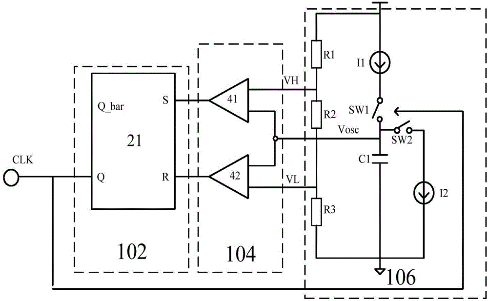
technical field [0001] The invention relates to the field of circuits, in particular to a clock signal generating circuit. Background technique [0002] With the development of semiconductor technology, the working speed of the chip is getting higher and higher, and the requirements for the clock system are getting stricter. For high-speed and high-precision application environments, the delay error of the clock signal generation circuit has an increasingly prominent impact on clock accuracy and cannot be ignored. [0003] The on-chip clock signal generation circuit based on the comparator is widely used in actual chips because of its simple implementation and high reliability. Such as figure 1 As shown, the current clock signal generation circuit mainly includes: signal shaping circuit 102 (RS flip-flop), threshold comparison circuit 104 (comparator 41 (CMP1), comparator 42 (CMP2)), delay generation circuit 106 (constant current source I1 and I2, capacitor C1). The sign...

Claims


Application Information

Patent Timeline
IPC IPC(8): H03K3/023H03K4/501
Inventor 袁莹莹陈东亮
Owner SG MICRO
Learn More