Reliable squirrel-cage rotor

A rotor and cage-shaped technology, applied in the field of cage-shaped rotors, can solve problems such as crack formation

Active Publication Date: 2015-08-26
SIEMENS AG
View PDF8 Cites 1 Cited by
  • Summary
  • Abstract
  • Description
  • Claims
  • Application Information

AI Technical Summary

Problems solved by technology

There the problem of the tendency for cracks to form at the transition between the short-circuit ring and the rotor rod to oc

Method used


Image

  • Reliable squirrel-cage rotor
  • Reliable squirrel-cage rotor
  • Reliable squirrel-cage rotor

Examples


Embodiment Construction

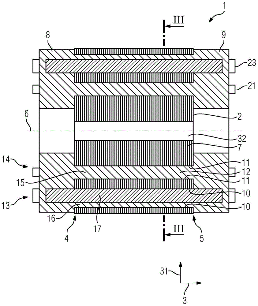
[0072] figure 1 An embodiment of a cage rotor 1 is shown, comprising a rotor plate stack 2 extending in the axial direction 3 from a first axial end 4 along the axis of rotation to a second axial end 5 and having a Lamination 7 layered in axial direction 3 . The cage rotor 1 also has a short-circuit ring 8 which surrounds the axis of rotation 6 and is arranged at the first axial end 4 , and a further short-circuit ring 9 which surrounds the axis of rotation 6 and is arranged at the second axial end Part 9 on. The short-circuit ring 8 and the further short-circuit ring 9 comprise the first material. The first material is suitable for manufacturing a cage rotor by die casting and comprises aluminum in this exemplary embodiment. The laminations 7 of the rotor lamination stack 2 each have a first punching 10 which forms the edge of a groove 16 of the rotor lamination stack which extends from the first axial end 4 to the second axial end 4 . End 5. The laminations 7 also each ...


PUM


Abstract

Cage rotor (1) comprises: a rotor core (2) which extends in an axial direction from a first axial end (4) to a second axial end (5) along an axis of rotation and has the coated plates in the axial direction; a short circuit ring which surrounds the rotational axis and which is disposed at the first axial end; and an additional short circuit ring which surrounds the rotational axis and which is arranged at the second axial end. The short-circuit ring and the additional short ring comprise a first material, in which the sheets respectively have first punching. Cage rotor (1) comprises: a rotor core (2) which extends in an axial direction from a first axial end (4) to a second axial end (5) along an axis of rotation and has the coated plates in the axial direction; a short circuit ring which surrounds the rotational axis and which is disposed at the first axial end; and an additional short circuit ring which surrounds the rotational axis and which is arranged at the second axial end. The short-circuit ring and the additional short ring comprise a first material, in which the sheets respectively have first punching, which forms the edges of the grooves of the rotor core extending from the first axial end to the second axial end. The plates respectively have a second punching which forms the edges from a passage extending from the first axial end to the second axial end. The first punching is located in an outer region of the plates, and the second punching is in an inner region of the plates. The passage is filled with a filling material from the first material, which is integrally connected to the short-circuit ring, and the additional short-circuit ring. Independent claims are also included for: (1) an electrical machine (50), comprising a squirrel-cage rotor; (2) producing a squirrel-cage rotor comprising receiving the filler material at least partially through the passage to the second axial end; and (3) series of electrical machines, comprising at least one first electrical machine, which comprises a first cage rotor and at least one second electrical machine, where the second electrical machine having a squirrel-cage version with a rotor core variant comprising a first punching and second punching. The plates edges of grooves of rotor core variant, respectively form first punching which extend from a first axial end of the rotor core variant to a second axial end of the rotor core variant, The edges from an open passage of the rotor core variant form the respective second punching of the plates, which runs from the first axial end of the rotor core variant for the second axial end of the rotor core variant.

Description

technical field [0001] The invention relates to a cage rotor according to the preamble of claim 1 , an electric machine comprising a cage rotor, and a set of electric machines comprising at least one first electric machine with a cage rotor. Furthermore, the invention relates to a method for producing a cage rotor. Background technique [0002] Such a cage rotor is known from DE 199 01 195 A1. There, the problem of the tendency for cracks to form at the transition between the short-circuit ring and the rotor rod to occur during the one-piece production of the rotor rod and the short-circuit ring by the aluminum die-casting process is solved. To solve this problem, spacer elements are cast into the die-cast cage windings at the left and right ends between the rotor lamination and the short-circuit ring. In DE 199 01 195 A1, the problem of the lack of ventilation of the rotor is also solved in that the laminations of the rotor lamination have cooling holes for forming coolin...

Claims


Application Information

Patent Timeline
IPC IPC(8): H02K17/18B22D19/00H02K17/20H02K15/00H02K1/32
CPCH02K17/185H02K2213/12H02K17/205B22D17/20H02K15/0012B22D19/0054H02K1/32H02K17/20H02K17/18
Inventor 康拉德·布兰德尔西格弗里德·菲希特纳帕特里克·彼得罗夫斯基马丁·沙勒
Owner SIEMENS AG
Why Eureka
Try Eureka