
A welding machine doing circular motion

A circular motion, welding machine technology, applied in the characteristics of electrodes, welding equipment, welding equipment, etc., can solve the problem of high failure rate of battery welding, high battery rotation accuracy, and battery clamping can not be too tight. , to achieve the effect of reducing production cost, improving repeat positioning accuracy, and reducing failure rate

Active Publication Date: 2017-04-19
武汉力兴(火炬)电源有限公司
View PDF4 Cites 0 Cited by
  • Summary
  • Abstract
  • Description
  • Claims
  • Application Information

AI Technical Summary

Problems solved by technology

Due to the relative movement between the battery and the fixture and the electrode of the argon arc welding machine during the welding process of the battery, and the clamping of the battery should not be too tight, and the operator will install the clamp too tightly, so it is very difficult to take the battery
Therefore, the welding machine is very prone to poor electrode contact during work. In addition, the way the battery is clamped makes the rotation accuracy of the battery impossible to be very high, so that the unqualified rate of battery welding remains high. In severe cases, it may even cause the welding machine to fail. normal work

Method used


Image

  • A welding machine doing circular motion
  • A welding machine doing circular motion
  • A welding machine doing circular motion

Examples


Embodiment Construction

[0024] The present invention will be further described in detail below in conjunction with the accompanying drawings and specific embodiments to facilitate a clear understanding of the present invention, but they do not limit the present invention.

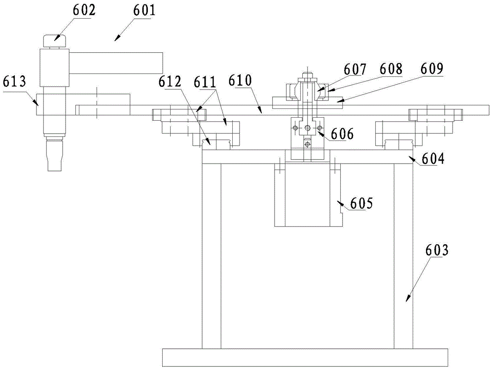
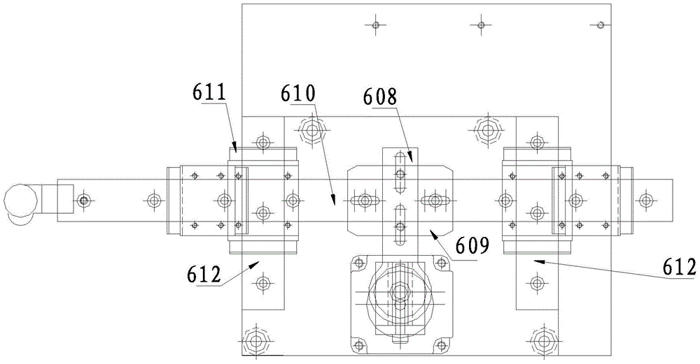
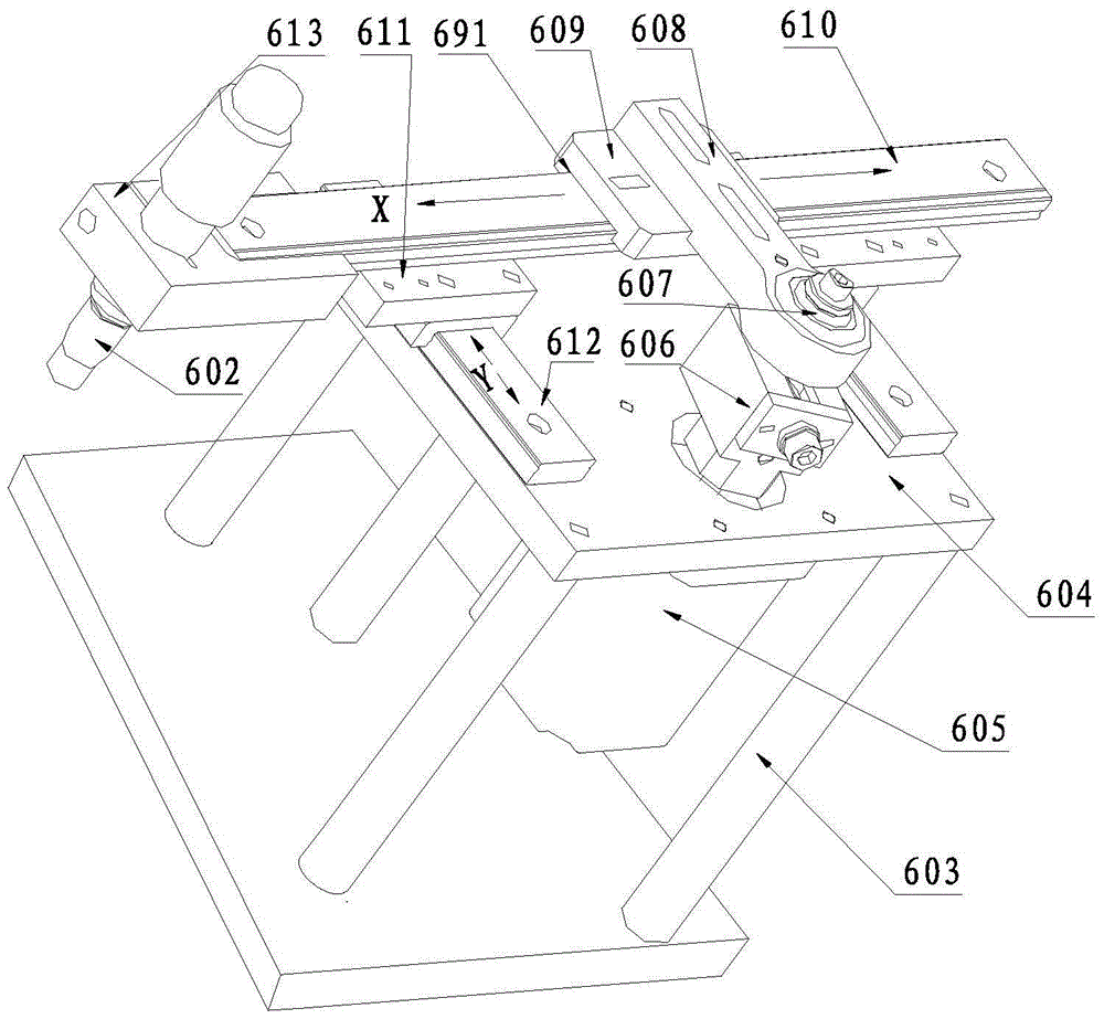
[0025] Such as figure 1 — image 3 As shown, the welding machine 601 of the present invention includes a welding torch base frame 603, a fixing plate 604 arranged on the welding torch base frame 603, a stepping motor 605 fixed on the bottom of the fixing plate 604, and the output shaft of the stepping motor 605 passes through the fixing plate 604 and the The bottom of the R adjustment device 606 is connected, and the top of the R adjustment device 606 is connected to a spherical bearing 607. The spherical bearing 607 is hinged to one end of the connecting rod 608, and the other end of the connecting rod 608 is fixed on the adjustable connecting plate 609. The adjustable connecting plate 609 is slidingly connected to the X On the ...


PUM


Abstract

The invention relates to a welding machine doing circular motion, and belongs to the technical field of lithium argon battery manufacturing. The welding machine comprises a welding gun bottom frame, a fixed plate arranged on the welding gun bottom frame and a stepping motor fixed to the bottom of the fixed plate. An output shaft of the stepping motor penetrates through the fixed plate to be connected with the bottom of an R adjusting device, the top of the R adjusting device is connected with a spherical bearing, the spherical bearing is hinged to one end of a connecting rod, and the other end of the connecting rod is fixed to an adjustable connecting plate. The adjustable connecting plate is in sliding connection with an X-direction sliding rail, the bottom of the X-direction sliding rail is in sliding connection with two parallel Y-direction sliding rails through connecting blocks, the end of the X-direction sliding rail is connected with a welding gun seat, and a welding gun is fixed to the welding gun seat. The welding gun is driven by the motor to do circular motion, the rotating precision of the welding gun can be guaranteed, a processed battery is clamped and fixed by a clamp pushed by an air cylinder, the battery is clamped by the air cylinder, precision is greatly improved, and almost no displacement is generated.

Description

technical field [0001] The invention belongs to the technical field of lithium-argon battery manufacturing, and in particular relates to a circular motion welding machine. Background technique [0002] The welding of the existing lithium-argon battery shell and cover all adopts argon arc welding, and its specific manufacturing process is that the welding torch is fixed, and the battery is installed in the fixture and rotates around the axis. Due to the relative movement between the battery and the clamp and the electrode of the argon arc welding machine during the welding process of the battery, and the clamping of the battery should not be too tight, and the clamping is too tight for the operator to install, so it is very difficult to take the battery. Therefore, the welding machine is very prone to poor electrode contact during work. In addition, the way the battery is clamped makes the rotation accuracy of the battery impossible to be very high, so that the unqualified ra...

Claims


Application Information

Patent Timeline
Patent Type & Authority Patents(China)
IPC IPC(8): B23K9/28B23K101/36
CPCB23K9/12B23K9/28B23K9/287B23K37/0247B23K37/0252B23K2101/36
Inventor 何汉成
Owner 武汉力兴(火炬)电源有限公司
Learn More