Special vehicle power system based on dual-end output work/traveling driving motor

A technology for driving motors and power systems, which is applied in electric vehicles, control drives, auxiliary drives, etc., can solve the problems of high power demand of the main drive motor, inconvenient layout of special vehicles, idle waste of operation motors, etc., so as to improve braking performance. Energy recovery rate, beneficial to reasonable layout, and the effect of avoiding idle waste

Inactive Publication Date: 2015-09-02
SHANDONG UNIV OF TECH
View PDF6 Cites 2 Cited by
  • Summary
  • Abstract
  • Description
  • Claims
  • Application Information

AI Technical Summary

Problems solved by technology

[0002] Existing pure electric special vehicles using the main and auxiliary dual-motor drive system, when in the working state, the main drive motor drives the traveling device of the main drive shaft of the special vehicle, and the auxiliary motor drives the operation device of the special vehicle for operation; in the non-operating state, the main drive motor The auxiliary motor of the traveling device that drives the main drive shaft of the special vehicle does not work; as the special vehicle operates at a low speed, the power required by the main drive motor is small. If it is matched with a high-power main drive motor, it will easily lead to waste of motor power; In the working

Method used


Image

  • Special vehicle power system based on dual-end output work/traveling driving motor
  • Special vehicle power system based on dual-end output work/traveling driving motor
  • Special vehicle power system based on dual-end output work/traveling driving motor

Examples


Example Embodiment

[0024] Example 1

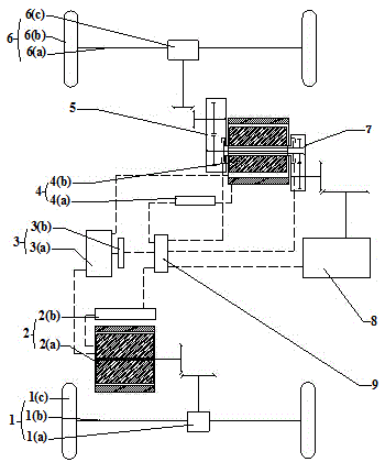
[0025] This embodiment discloses a special vehicle power system based on a double-ended output work / travel drive motor, including a vehicle controller 9, a main drive motor and its controller 2, a work / travel drive motor and its controller 4, and a first clutch Transmission device 7, second clutch transmission device 5;
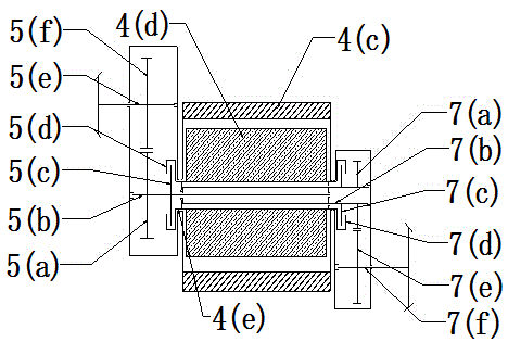
[0026] The work / running drive motor 4(b) includes a stator 4(c), a rotor 4(d), and a rotor output shaft 4(e); the first clutch transmission device 7 includes a first clutch 7(c) , The first clutch input plate 7 (d), the first driving shaft 7 (b), the first driving shaft driving gear 7 (a), the first driven shaft 7 (f), the first driven shaft driven gear 7 (e); The second clutch transmission device 5 includes a second clutch 5 (c), a second clutch input disc 5 (d), a second driving shaft 5 (b), a second driving shaft driving gear 5 (a ), the second driven shaft 5(e), the second driven shaft driven gear 5(f);

[0027] The rotor output shaft 4(e) ...

Example Embodiment

[0029] Example 2

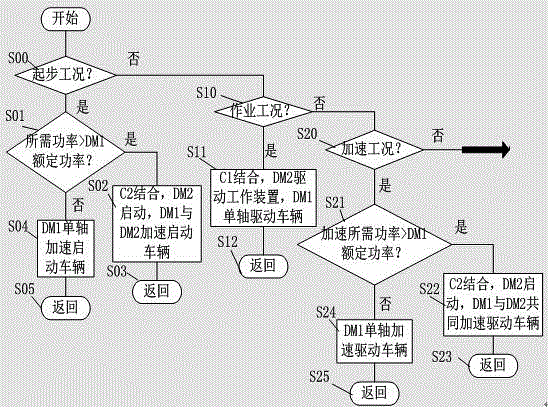
[0030] This embodiment discloses a special vehicle power system control strategy based on a double-ended output working motor. The vehicle controller 9 in the power system controls the coordination of the entire power system, and can judge and select the appropriate Drive mode control strategy, the drive mode of the special vehicle includes main drive motor 2(a) single motor drive mode, main drive motor 2(a) separate braking mode, operation mode, main drive motor 2(a) and work motor 4( b) Timely four-wheel drive mode, combined braking mode of main drive motor 2(a) and work motor 4(b), the power system control strategy steps are as follows:

[0031] (1) The power control system first judges the operating mode signal of the special vehicle. The vehicle controller 9 judges whether it is the starting operating condition according to the key position signal, the transmission gear signal, the accelerator pedal position signal and the vehicle speed signal: In the start...


PUM


Abstract

The invention discloses a special vehicle power system based on a dual-end output work/traveling driving motor. The special vehicle power system comprises a vehicle control unit, a main driving motor and its controller, a driving/traveling driving motor and its controller, a first clutch transmission device, and a second clutch transmission device; the vehicle control unit controls the coordinating work of the whole power system, and the main driving motor is connected to a main driving shaft walking device; during the work, the driving/traveling driving motor is used as a working driving device; when the vehicle accelerates and climbs, the driving/traveling driving motor can also be used as an assistant driving device; first and second clutch input disks in the first and second clutch transmission devices are respectively installed at both ends of the output shaft of a work/traveling driving motor rotor, a first driven shaft is connected to a working device and a second driven shaft is connected to an assistant driving shaft traveling device; the system can realize the functional conversion of the assistant driving traveling and work of the work/traveling driving motor; on the basis of ensuring the dynamic property of the whole vehicle, the system can reduce the power of the main driving motor and optimize the vehicle energy utilization rate.

Description

technical field [0001] The invention relates to a power system of a special vehicle based on a double-terminal output operation / travel drive motor. Background technique [0002] Existing pure electric special vehicles using the main and auxiliary dual-motor drive system, when in the working state, the main drive motor drives the traveling device of the main drive shaft of the special vehicle, and the auxiliary motor drives the operation device of the special vehicle for operation; in the non-operating state, the main drive motor The auxiliary motor of the traveling device that drives the main drive shaft of the special vehicle does not work; as the special vehicle operates at a low speed, the power required by the main drive motor is small. If it is matched with a high-power main drive motor, it will easily lead to waste of motor power; In the working state, when the special vehicle is running at high speed, accelerating rapidly, or climbing a steep slope, the main drive mot...

Claims


Application Information

Patent Timeline
IPC IPC(8): B60K17/356B60K17/02B60L15/00B60K25/06
CPCY02T10/84
Inventor 高松杨明红孙宾宾
Owner SHANDONG UNIV OF TECH
Why Eureka
Try Eureka