Powder feeder

A powder feeder and powder tank technology, used in conveyors, conveying bulk materials, transportation and packaging, etc., can solve the problems of easy wear of the screw conveyor shaft, damage to the motor, low conveying efficiency, etc., to improve the working capacity of the equipment, The effect of eliminating equipment maintenance and improving conveying efficiency

Pending Publication Date: 2015-09-02
HENAN CHAOBEI ENG EQUIP
View PDF8 Cites 1 Cited by
  • Summary
  • Abstract
  • Description
  • Claims
  • Application Information

AI Technical Summary

Problems solved by technology

[0002] The traditional powder feeder consists of a powder tank, a powder feeding pipeline, and a screw powder feeding shaft. The bottom of the powder tank is connected to the powder feeding pipeline. When agglomerated powder is used, it may damage electrical equipment such as motors

Method used


Image

  • Powder feeder

Examples


Embodiment Construction

[0007] The present invention will be further described below in conjunction with the accompanying drawings and embodiments.

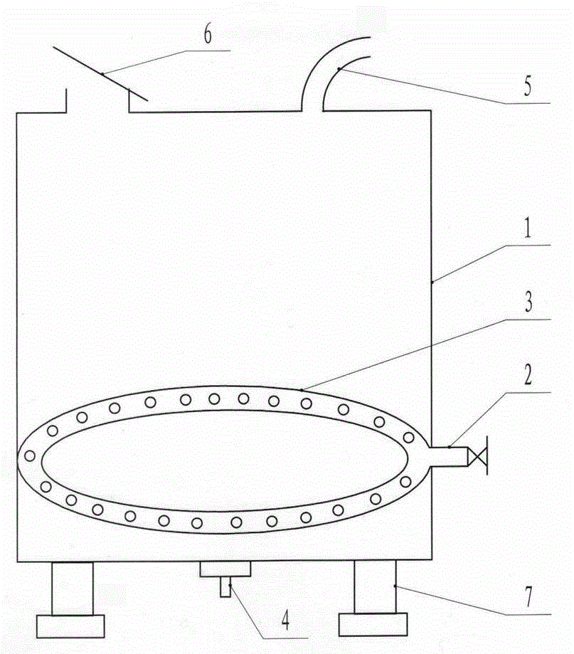
[0008] According to the accompanying drawings: the top of the powder tank body 1 is respectively provided with a charging port 6 and a discharge port 5, and a pneumatic vibrator 4 and a base 7 are respectively installed at the bottom thereof. A circular air duct 3 is mainly installed on the bottom inner wall of the powder tank body 1 cavity. Blow the powder in the direction and then spray it to the outlet 5.

[0009] When in use, when the powder is put into the back cover from the charging port 6, start the pneumatic vibrator 4 and send air from the air inlet 2, and the wind blows the powder evenly through the small holes on the circular air duct 3, and then blows the powder evenly from the discharge port. Spray from the mouth, and spray the powder evenly on the panel without interruption.


PUM


Abstract

The invention discloses a powder feeder, and mainly relates to a powder spraying device. The powder feeder comprises a powder tank, an annular air duct, an air inlet, a discharging opening, a charging opening and a pneumatic vibrator, and is characterized in that the air inlet is formed in the bottom of the inner part of a cavity of the powder tank and is connected with the annular air duct mounted on the inner wall of the tank; a plurality of holes are drilled in upper, lower and inner sides of the annular air duct so that the compressed air blows the powder; the discharging opening is formed in the upper part of the tank; the air vibrator is mounted at the bottom of the tank so that the powder stuck on the tank wall drops and is conveyed uniformly. The powder feeder is simple in structure, reasonable in design and convenient to manufacture; the powder feeder can be connected with an air compressor by only one air duct, without any electrical power equipment; compared with the traditional powder feeder, the powder feeder greatly improves the conveying efficiency, avoids equipment maintenance, improves the operational capability of the equipment, and can realize the continuous and uniform conveying of powder.

Description

technical field [0001] The invention relates to a powder injection device. Background technique [0002] The traditional powder feeder consists of a powder tank, a powder feeding pipeline, and a screw powder feeding shaft. The bottom of the powder tank is connected to the powder feeding pipeline. When agglomerated powder is used, it may damage electrical equipment such as motors. Contents of the invention [0003] The object of the present invention is to solve the deficiencies of the prior art, and provide a powder feeder which has a simple structure, is convenient to manufacture, and has greatly improved conveying efficiency, and can realize uninterrupted and uniform conveying of powder. [0004] In order to achieve the above object, the technical solution of the present invention is: a powder feeder, which consists of a powder tank, an annular air duct, an air inlet, a material outlet, a material charging port, and a pneumatic vibrator. It is characterized in that: th...

Claims


Application Information

Patent Timeline
Patent Type & Authority Applications(China)
IPC IPC(8): B65G53/00
Inventor 胡鹏飞赵焕军
Owner HENAN CHAOBEI ENG EQUIP
Why Eureka
Try Eureka